67
RTAA-IOM-3
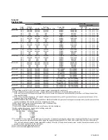
Table 10
Electrical Data
Unit Wiring
Motor Data
Fans (Ea)
Rated
MCA (3)
Rec Time
Comp. (Ea)
Qty.
Qty.
Unit Size
Voltage
Ckt1/Ckt2(1)
MOP(2)
Delay or RDE4)
Qty.
RLA(5)
LRA(8)
(11)
(12)
kW
FLA kW(7)
RTAA 130
200
383/389
600/600
500/500
2
280/280
1689/1689
10
11
1.3
6.5
0.8
230
383/389
600/600
500/500
2
280/280
1689/1689
10
11
1.3
6.5
0.8
460
306
400
350
2
122/122
633/633
10
11
1.3
2.8
0.8
575
246
300
300
2
98/98
512/512
10
11
1.3
2.3
0.8
RTAA 140
200
383/389
600/600
500/500
2
280/280
1689/1689
10
11
1.3
6.5
0.8
230
383/389
600/600
500/500
2
280/280
1689/1689
10
11
1.3
6.5
0.8
460
306
400
350
2
122/122
633/633
10
11
1.3
2.8
0.8
575
246
300
300
2
98/98
512/512
10
11
1.3
2.3
0.8
RTAA 155
200
422/389
700/600
500/500
2
306/280
2044/1689
11
12
1.3
6.5
0.8
230
422/389
700/600
500/500
2
306/280
2044/1689
11
12
1.3
6.5
0.8
460
322
450
400
2
133/122
766/633
11
12
1.3
2.8
0.8
575
260
350
300
2
107/98
611/512
11
12
1.3
2.3
0.8
RTAA 170
200
515/389
800/600
700/500
2
375/280
2391/1689
12
13
1.3
6.5
0.8
230
515/389
800/600
700/500
2
375/280
2391/1689
12
13
1.3
6.5
0.8
460
363
500
450
2
163/122
896/633
12
13
1.3
2.8
0.8
575
292
400
350
2
131/987
25/512
12
13
1.3
2.3
0.8
RTAA 185
200
515/428
800/700
700/600
2
375/306
2391/2044
13
14
1.3
6.5
0.8
230
515/428
800/700
700/600
2
375/306
2391/2044
13
14
1.3
6.5
0.8
460
376
500
450
2
163/133
896/766
13
14
1.3
2.8
0.8
575
303
400
350
2
131/107
725/611
13
14
1.3
2.3
0.8
RTAA 200
200
514/514
800/800
700/700
2
375/375
2391/2391
14
14
1.3
6.5
0.8
230
514/514
800/800
7001700
2
375/375
2391/2391
14
14
1.3
6.5
0.8
460
406
500
450
2
163/163
896/896
14
14
1.3
2.8
0.8
575
327
450
400
2
131/131
725/725
14
14
1.3
2.3
0.8
RTAA 240
460
303/224
400/350
350/300
3
122-122/163
633-633/896
N/A
17
1.3
2.8
1.0
575
244/180
300/300
300/225
3
98-98/131
512-512/725
N/A
17
1.3
2.3
1.0
RTAA 270
460
360/224
500/350
450/300
3
163-122/163
896-633/896
N/A
19
1.3
2.8
1.0
575
290/180
400/300
350/225
3
131-98/131
725-512/725
N/A
19
1.3
2.3
1.0
RTAA 300
460
406/224
500/350
450/300
3
163-163/163
896-896/896
N/A
21
1.3
2.8
1.0
575
327/180
450/300
400/225
3
131-131/131
725-725/725
N/A
21
1.3
2.3
1.0
RTAA 340
460
303/406
400/500
350/450
4
122-122/163-163
633-633/896-896
N/A
24
1.3
2.8
1.0
575
244/327
300/450
300/400
4
98-98/131-131
512-512/725-725
N/A
24
1.3
2.3
1.0
RTAA 370
460
360/406
500/500
450/450
4
163-122/163-163
896-633/896-896
N/A
26
1.3
2.8
1.0
575
290/327
400/450
350/400
4
131-98/131-131
725-512/725-725
N/A
26
1.3
2.3
1.0
RTAA 400
460
406/406
500/500.
450/450
4
163-163/163-163
896-896/896-896
N/A
28
1.3
2.8
1.0
575
327/327
450/450
400/400
4
131-131/131-131
725-725/725-725
N/A
28
1.3
2.3
1.0
Notes:
(1) Low voltage units (200 & 230 volt) require separate power connections for each circuit.
(2) MOP - Maximum Overcurrent Protection - may be either fused (UL/CSA) or with circuit breakers (CSA only).
MOP = 225 percent of the largest compressor RLA plus 100 percent of the second compressor RLA plus the sum of the condenser fans
FLAs per NEC 440-22.
(3) MCA - Minimum Circuit Ampacity - 125 percent of largest compressor RLA plus 100 percent of second compressor plus the sum of the
condenser fans FLAs per NEC 440-33.
(4) RECOMMENDED TIME DELAY OR DUAL ELEMENT (RDE) FUSE SIZE: 150 percent of the largest compressor RLA plus 100 percent of the
second compressor RLA and the sum of the condenser tan FLAs.
(5) RLA - Rated Load Amps - rated in accordance with UL Standard 465.
(6) Local codes may take precedence.
(7) Control kW includes operational controls only. Does not include heat tapes.
(8) LRA - Locked Rotor Amps - based on full winding start units.
(9) VOLTAGE UTILIZATION RANGE:
Rated Voltage
Utilization Range
200
180-220
230
208-254
460
414-506
575
516.633
(10) A 11 5/60/1, 15 amp. customer provided power connection is required to operate the unit controls. A separate 115(60/1, 15 amp. customer
provided power connection is also needed to power the evaporator heat tape (RTAA 130-200 = 420 watts, RTAA 240-400 = 840 wafts @
120 volts) and optional Domestic Water Heater (420 watts @ 120 volts.). If the optional control power is used, the customer needs only to
provide a power connection for the heat tapes.
(11) 15 F minimum starting/operating ambient.
(12) 0 F minimum starting/operating ambient
Содержание RTAA-130
Страница 2: ... American Standard Inc 1991 ...
Страница 8: ...8 RTAA IOM 3 ...
Страница 13: ...13 RTAA IOM 3 Figure 3 Typical RTAA Packaged Unit 240 400 Tons Control Panel Evaporator Outlet Inlet ...
Страница 24: ...24 RTAA IOM 3 ...
Страница 26: ...26 RTAA IOM 3 Figure 9 Dimensions and Clearances for RTAA Packaged Unit 130 to 200 Ton RTAA SU 1000E ...
Страница 27: ...27 RTAA IOM 3 Figure 10 Dimensions and Clearances for RTAA Packaged Unit 240 300 Ton RTAA SU 1001C ...
Страница 28: ...28 RTAA IOM 3 Figure 11 Dimensions and Clearances for RTAA Packaged Unit 340 to 400 Ton RTAA SU 1002C ...
Страница 38: ...38 RTAA IOM 3 RTAA SA 2002C Figure 19 Spring Isolator Placement for Typical RTAA Packaged Unit 240 400 Tons ...
Страница 46: ...46 RTAA IOM 3 Figure 24 Typical Domestic Water Heater Piping Figure 25 Typical Domestic Water Heater Piping ...
Страница 50: ...50 RTAA IOM 3 Figure 30 Refrigerant Circuit Identification ...
Страница 52: ...52 RTAA IOM 3 Figure 31 Remote Evaporator Piping Example ...
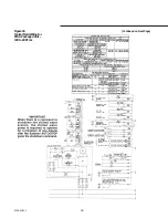
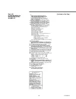
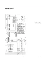
Страница 58: ...58 RTAA IOM 3 Continued on Next Page Figure 34 Typical Field Wiring for RTAA Packaged Unit 130 to 200 Tons ...
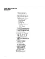
Страница 59: ...59 RTAA IOM 3 Continued from Previous Page See Notes on Next Page ...
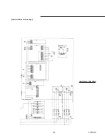
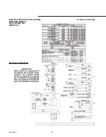
Страница 61: ...61 RTAA IOM 3 Figure 35 Typical Field Wiring for RTAA Packaged Unit 240 400 Tons Continued on Next Page ...
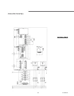
Страница 63: ...63 RTAA IOM 3 Continued from Previous Page See Notes on Page 61 ...
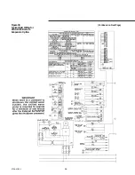
Страница 64: ...64 RTAA IOM 3 Figure 36 Typical Field Wiring for RTAA With Remote Evaporator Option Continued on Next Page ...
Страница 65: ...65 RTAA IOM 3 Continued from Previous Page See Notes on Page 61 ...
Страница 76: ...76 RTAA IOM 3 ...
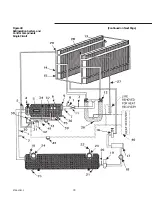
Страница 78: ...78 RTAA IOM 3 Figure 40 Refrigeration System and Control Components Single Circuit Continued on Next Page ...
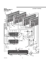
Страница 80: ...80 RTAA IOM 3 Figure 41 Refrigeration System and Control Components Duplex Circuit Continued on Next Page ...
Страница 92: ...92 RTAA IOM 3 Figure 51 Operator Interface Controls ...
Страница 120: ...120 RTAA IOM 3 ...
Страница 126: ...126 RTAA IOM 3 Figure 56 Unit Sequence of Operation RTAA 240 to 400 Tons Continued on Next Page ...
Страница 127: ...127 RTAA IOM 3 Continued from Previous Page 2307 1566C ...
Страница 128: ...128 RTAA IOM 3 Figure 57 Unit Sequence of Operation RTAA 130 to 200 Tons 2306 9122A ...
Страница 132: ...132 RTAA IOM 3 Figure 58 Operator s Log ...
Страница 138: ...138 RTAA IOM 3 ...

