129
RTAA-IOM-3
Unit Shutdown
Procedures
Temporary Shutdown
and Restart
To shut the unit down for a short time,
use the following procedure:
1. Move the Chiller Switch to STOP/
RESET. The compressors will
continue to operate and, after
unloading for 20 seconds, will stop
when the compressor contactors de-
energize. The condenser fans will be
de-energized at this time.
2. The unit disconnect switch and unit
mounted disconnect (if installed)
should remain closed to keep the
compressor sump heaters energized.
3. Maintain power to keep the
evaporator and Domestic Water
Heater heat tape(s) energized.
4. Stop the chilled water circulation by
turning off the chilled water pump.
To restart the unit after a temporary
shutdown, restart the chilled water
pump and move the Chiller Switch to
either of the AUTO positions. The unit
will start normally, provided the
following conditions exist:
1. The UCM must receive a call for
cooling and the differential- to-start
must be above the setpoint.
2. All system operating interlocks and
safety circuits must be satisfied.
Extended Shutdown
Procedure
The following procedure is to be
followed if the system is to be taken out
of service for an extended period of
time, e.g. seasonal shutdown:
1. Test the condenser and high-side
piping for refrigerant leakage.
2. Open the electrical disconnect
switches for the chilled water pump.
Lock the switch in the “OPEN”
position.
Caution: Lock the chilled water
pump disconnect open to prevent
pump damage.
3. Close all chilled water supply valves.
Drain the chilled water from the
evaporator. If the unit will be
exposed to freezing ambient
conditions, flush the evaporator with
an antifreeze solution and energize
the evaporator heat tape.
Caution: To prevent damage to the
evaporator by freezing, flush the
evaporator with an antifreeze
solution and energize the
evaporator heat tape.
4. Drain the Domestic Water Heater and
any exposed system piping to
prevent the possibility of freeze-up.
Use the pressure tap on the water
outlet to force compressed air
through the water coils of the unit
and assure that no water blocks any
of the tubes. Be certain that the drain
valve on the water inlet is open
before applying compressed air to
the water coils. Energize the
Domestic Water Heater heat tape.
Caution: To prevent damage to the
Domestic Water Heater by
freezing, blow out water from coils
and energize the Domestic Water
Heater heat tape.
5. Open the unit main electrical
disconnect and unit-mounted
disconnect (if installed) and lock on
the “OPEN” position. If optional
control power transformer is not
installed, open and lock the 115 V
disconnect.
Caution: Lock the disconnects on
the “OPEN” position to prevent
accidental start-up and damage to
the system when it has been setup
for extended shutdown.
6. At least every three months
(quarterly), check the pressure in the
unit to verify that the refrigerant
charge is intact.
Содержание RTAA-130
Страница 2: ... American Standard Inc 1991 ...
Страница 8: ...8 RTAA IOM 3 ...
Страница 13: ...13 RTAA IOM 3 Figure 3 Typical RTAA Packaged Unit 240 400 Tons Control Panel Evaporator Outlet Inlet ...
Страница 24: ...24 RTAA IOM 3 ...
Страница 26: ...26 RTAA IOM 3 Figure 9 Dimensions and Clearances for RTAA Packaged Unit 130 to 200 Ton RTAA SU 1000E ...
Страница 27: ...27 RTAA IOM 3 Figure 10 Dimensions and Clearances for RTAA Packaged Unit 240 300 Ton RTAA SU 1001C ...
Страница 28: ...28 RTAA IOM 3 Figure 11 Dimensions and Clearances for RTAA Packaged Unit 340 to 400 Ton RTAA SU 1002C ...
Страница 38: ...38 RTAA IOM 3 RTAA SA 2002C Figure 19 Spring Isolator Placement for Typical RTAA Packaged Unit 240 400 Tons ...
Страница 46: ...46 RTAA IOM 3 Figure 24 Typical Domestic Water Heater Piping Figure 25 Typical Domestic Water Heater Piping ...
Страница 50: ...50 RTAA IOM 3 Figure 30 Refrigerant Circuit Identification ...
Страница 52: ...52 RTAA IOM 3 Figure 31 Remote Evaporator Piping Example ...
Страница 58: ...58 RTAA IOM 3 Continued on Next Page Figure 34 Typical Field Wiring for RTAA Packaged Unit 130 to 200 Tons ...
Страница 59: ...59 RTAA IOM 3 Continued from Previous Page See Notes on Next Page ...
Страница 61: ...61 RTAA IOM 3 Figure 35 Typical Field Wiring for RTAA Packaged Unit 240 400 Tons Continued on Next Page ...
Страница 63: ...63 RTAA IOM 3 Continued from Previous Page See Notes on Page 61 ...
Страница 64: ...64 RTAA IOM 3 Figure 36 Typical Field Wiring for RTAA With Remote Evaporator Option Continued on Next Page ...
Страница 65: ...65 RTAA IOM 3 Continued from Previous Page See Notes on Page 61 ...
Страница 76: ...76 RTAA IOM 3 ...
Страница 78: ...78 RTAA IOM 3 Figure 40 Refrigeration System and Control Components Single Circuit Continued on Next Page ...
Страница 80: ...80 RTAA IOM 3 Figure 41 Refrigeration System and Control Components Duplex Circuit Continued on Next Page ...
Страница 92: ...92 RTAA IOM 3 Figure 51 Operator Interface Controls ...
Страница 120: ...120 RTAA IOM 3 ...
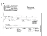
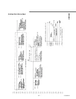
Страница 126: ...126 RTAA IOM 3 Figure 56 Unit Sequence of Operation RTAA 240 to 400 Tons Continued on Next Page ...
Страница 127: ...127 RTAA IOM 3 Continued from Previous Page 2307 1566C ...
Страница 128: ...128 RTAA IOM 3 Figure 57 Unit Sequence of Operation RTAA 130 to 200 Tons 2306 9122A ...
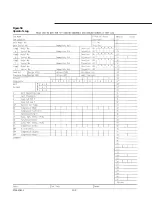
Страница 132: ...132 RTAA IOM 3 Figure 58 Operator s Log ...
Страница 138: ...138 RTAA IOM 3 ...

