84
RTAA-IOM-3
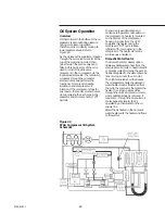
Slide Valve Movement
Movement of the slide valve piston
determines slide valve position which,
in turn, regulates compressor capacity.
Oil flow into and out of the cylinder
governs piston movement, and is
controlled by the normally-closed, load
and unload solenoid valves.
The solenoid valves receive
momentary pulsating “load” and
“Unload” voltage signals from the
UCM based on system cooling
requirements. To load the compressor,
the UCM opens the load solenoid valve
while keeping the unload solenoid
valve closed. The pressurized oil flow
then enters the cylinder and forces the
slide valve to move over the rotors.
The compressor is unloaded when the
load solenoid valve is kept closed and
the unload solenoid valve is opened.
Oil “trapped” within the cylinder is
drawn out into the lower-pressure
suction area of the compressor. As the
pressurized oil leaves the cylinder, the
slide valve gradually moves away from
the rotors.
When both solenoid valves are closed,
the present level of compressor loading
is maintained.
Just prior to a normal compressor
shutdown, the unload solenoid valve is
energized and the slide valve moves to
the fully-unloaded position, so the unit
always starts fully unloaded.
Oil Filter
Each refrigerant circuit is equipped with
replaceable-element oil filters. The
filter(s) remove any impurities that
could foul the solenoid valve orifices
and compressor internal oil supply
galleries. This also prevents excessive
wear of compressor rotor and bearing
surfaces. Refer to the maintenance
portion of this manual for
recommended filter element
replacement intervals.
Condenser Fans
The RTAA Series offers either the 15 F
or 0 F ambient fan configuration. On
the 0 F ambient option, the lead fan(s)
on each circuit is a half-airflow (half-
pitch blade) fan(s). Half pitch fans have
a blade pitch of 150 and full pitch fans
have a blade pitch of 27°.
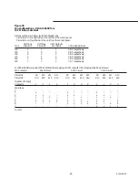
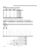
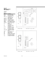
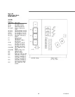
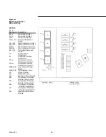
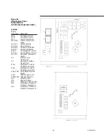
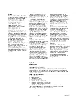
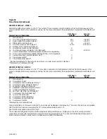
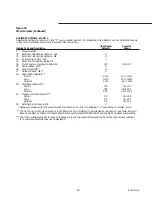
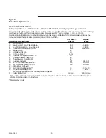
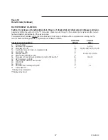
Figures 45 and 46 show the number of
fans installed on each model, the
designation of fan contactors and the
staging of fans as the UCM calls for
more condenser cooling. Fan staging is
a function of the difference between
the saturated condenser refrigerant
temperature and the saturated
evaporator refrigerant temperature,
which in turn is a function of the load
and ambient temperature. Any number
of fans can be operating at a given
time, depending on these variables.
Содержание RTAA-130
Страница 2: ... American Standard Inc 1991 ...
Страница 8: ...8 RTAA IOM 3 ...
Страница 13: ...13 RTAA IOM 3 Figure 3 Typical RTAA Packaged Unit 240 400 Tons Control Panel Evaporator Outlet Inlet ...
Страница 24: ...24 RTAA IOM 3 ...
Страница 26: ...26 RTAA IOM 3 Figure 9 Dimensions and Clearances for RTAA Packaged Unit 130 to 200 Ton RTAA SU 1000E ...
Страница 27: ...27 RTAA IOM 3 Figure 10 Dimensions and Clearances for RTAA Packaged Unit 240 300 Ton RTAA SU 1001C ...
Страница 28: ...28 RTAA IOM 3 Figure 11 Dimensions and Clearances for RTAA Packaged Unit 340 to 400 Ton RTAA SU 1002C ...
Страница 38: ...38 RTAA IOM 3 RTAA SA 2002C Figure 19 Spring Isolator Placement for Typical RTAA Packaged Unit 240 400 Tons ...
Страница 46: ...46 RTAA IOM 3 Figure 24 Typical Domestic Water Heater Piping Figure 25 Typical Domestic Water Heater Piping ...
Страница 50: ...50 RTAA IOM 3 Figure 30 Refrigerant Circuit Identification ...
Страница 52: ...52 RTAA IOM 3 Figure 31 Remote Evaporator Piping Example ...
Страница 58: ...58 RTAA IOM 3 Continued on Next Page Figure 34 Typical Field Wiring for RTAA Packaged Unit 130 to 200 Tons ...
Страница 59: ...59 RTAA IOM 3 Continued from Previous Page See Notes on Next Page ...
Страница 61: ...61 RTAA IOM 3 Figure 35 Typical Field Wiring for RTAA Packaged Unit 240 400 Tons Continued on Next Page ...
Страница 63: ...63 RTAA IOM 3 Continued from Previous Page See Notes on Page 61 ...
Страница 64: ...64 RTAA IOM 3 Figure 36 Typical Field Wiring for RTAA With Remote Evaporator Option Continued on Next Page ...
Страница 65: ...65 RTAA IOM 3 Continued from Previous Page See Notes on Page 61 ...
Страница 76: ...76 RTAA IOM 3 ...
Страница 78: ...78 RTAA IOM 3 Figure 40 Refrigeration System and Control Components Single Circuit Continued on Next Page ...
Страница 80: ...80 RTAA IOM 3 Figure 41 Refrigeration System and Control Components Duplex Circuit Continued on Next Page ...
Страница 92: ...92 RTAA IOM 3 Figure 51 Operator Interface Controls ...
Страница 120: ...120 RTAA IOM 3 ...
Страница 126: ...126 RTAA IOM 3 Figure 56 Unit Sequence of Operation RTAA 240 to 400 Tons Continued on Next Page ...
Страница 127: ...127 RTAA IOM 3 Continued from Previous Page 2307 1566C ...
Страница 128: ...128 RTAA IOM 3 Figure 57 Unit Sequence of Operation RTAA 130 to 200 Tons 2306 9122A ...
Страница 132: ...132 RTAA IOM 3 Figure 58 Operator s Log ...
Страница 138: ...138 RTAA IOM 3 ...

