110
RTAA-IOM-3
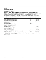
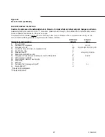
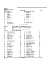
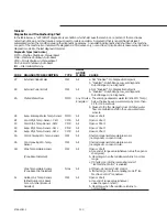
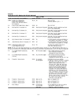
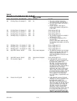
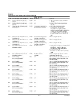
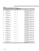
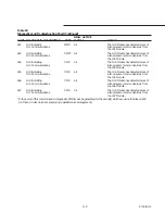
Table 18
Diagnostics and Troubleshooting Chart
In the table below, a “LATCHING” diagnostic is a condition which shall cause the machine or a portion of the machine as
noted to shut down and shall require a manual reset to restore operation. A diagnostic that is non-latching shall reset
automatically when the condition causing the diagnostic goes away. A non-latching diagnostic shall shut down the machine
or a part of the machine if so indicated. If a diagnostic is informative only, no machine or circuit action is taken except to load a
diagnostic code into the last diagnostic register.
Diagnostic Types (And Action)
MMR = Machine Shutdown, Manual Reset
MAR = Machine Shutdown, Auto Reset
CMR = Circuit Shutdown, Manual Reset
CAR = Circuit Shutdown, Auto Reset
IFW = Information/Warning
DIAG.
ACTIVE
CODE
DIAGNOSTIC DESCRIPTION
TYPE
MODES
CAUSE
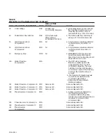
87
External Chilled Water
IFW
All
a. Not “Enabled”: No Diagnostics Setpoint
b. “Enabled”: Out-of-Range Low, set diagnostic.
Out-of-Range Hi, no diagnostic.
89
External Current Limit
IFW
All
a. Not “Enabled”: No Diagnostics Setpoint
b. “Enabled”: Out-of-Range Low, set diagnostic.
Out-of-Range Hi, no diagnostic.
8A
Chilled Water Flow
MMR
Any Circuit a. The entering evaporator water fell (Ent. Wtr. Temp.)
Energized
below the leaving evap. water temp. by more than
2 F for 100 F-seconds.
b. Causes to trip this diagnostic loss of chilled water
flow or a calibration shift in the evap. water temp.
sensors.
8E
Evap. Entering Water Temp. Sensor
MMR
All
Open or Short
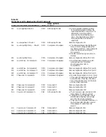
8F
Cond. Rfgt. Temp. Sensor - Ckt 1
CMR
All
Open or Short
90
Cord. Rfgt. Temp. Sensor - Ckt 2
CMR
All
Open or Short
93
Evap. Rfgt. Temp. Sensor - Ckt 1
CMR
All
Open or Short
94
Evap. Rfgt. Temp. Sensor - Ckt 2
CMR
All
Open or Short
9A
Cord. Entering Wtr. Temp. Sensor
IFW
All
Shorted condenser temperature sensor
(no diagnostic on open circuit).
9b
Cond. Leaving Wtr. Temp.
IFW
All
Shorted condenser temperature sensor
Sensor
(no diagnostic on open circuit).
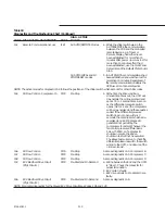
AO
Zone Temperature Sensor
IFW
All
Open or Short
a. Use end of range value (whatever value the open or
short gives).
(Zone Reset Selected)
b. Clear diag. when the resistance returns to normal
range.
c. If Shorted, go into the ice making mode if
“Ice Machine Control” is enabled.
Zone Temperature Sensor
None
All
a. If Open, do normal chiller control .
(Zone Reset Not Selected)
b. If Shorted, go into the ice making mode if “Ice
Machine Control” is enabled.
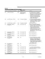
A1
Outdoor Air Temp. Sensor
IFW
All
Open or Short
(Either Outdoor Air Reset
a. Use end of range value (whatever
or Low Ambient Lockout
value the open or short).
Selected)
b. Clear diag. when the resistance returns to
normal range.
Содержание RTAA-130
Страница 2: ... American Standard Inc 1991 ...
Страница 8: ...8 RTAA IOM 3 ...
Страница 13: ...13 RTAA IOM 3 Figure 3 Typical RTAA Packaged Unit 240 400 Tons Control Panel Evaporator Outlet Inlet ...
Страница 24: ...24 RTAA IOM 3 ...
Страница 26: ...26 RTAA IOM 3 Figure 9 Dimensions and Clearances for RTAA Packaged Unit 130 to 200 Ton RTAA SU 1000E ...
Страница 27: ...27 RTAA IOM 3 Figure 10 Dimensions and Clearances for RTAA Packaged Unit 240 300 Ton RTAA SU 1001C ...
Страница 28: ...28 RTAA IOM 3 Figure 11 Dimensions and Clearances for RTAA Packaged Unit 340 to 400 Ton RTAA SU 1002C ...
Страница 38: ...38 RTAA IOM 3 RTAA SA 2002C Figure 19 Spring Isolator Placement for Typical RTAA Packaged Unit 240 400 Tons ...
Страница 46: ...46 RTAA IOM 3 Figure 24 Typical Domestic Water Heater Piping Figure 25 Typical Domestic Water Heater Piping ...
Страница 50: ...50 RTAA IOM 3 Figure 30 Refrigerant Circuit Identification ...
Страница 52: ...52 RTAA IOM 3 Figure 31 Remote Evaporator Piping Example ...
Страница 58: ...58 RTAA IOM 3 Continued on Next Page Figure 34 Typical Field Wiring for RTAA Packaged Unit 130 to 200 Tons ...
Страница 59: ...59 RTAA IOM 3 Continued from Previous Page See Notes on Next Page ...
Страница 61: ...61 RTAA IOM 3 Figure 35 Typical Field Wiring for RTAA Packaged Unit 240 400 Tons Continued on Next Page ...
Страница 63: ...63 RTAA IOM 3 Continued from Previous Page See Notes on Page 61 ...
Страница 64: ...64 RTAA IOM 3 Figure 36 Typical Field Wiring for RTAA With Remote Evaporator Option Continued on Next Page ...
Страница 65: ...65 RTAA IOM 3 Continued from Previous Page See Notes on Page 61 ...
Страница 76: ...76 RTAA IOM 3 ...
Страница 78: ...78 RTAA IOM 3 Figure 40 Refrigeration System and Control Components Single Circuit Continued on Next Page ...
Страница 80: ...80 RTAA IOM 3 Figure 41 Refrigeration System and Control Components Duplex Circuit Continued on Next Page ...
Страница 92: ...92 RTAA IOM 3 Figure 51 Operator Interface Controls ...
Страница 120: ...120 RTAA IOM 3 ...
Страница 126: ...126 RTAA IOM 3 Figure 56 Unit Sequence of Operation RTAA 240 to 400 Tons Continued on Next Page ...
Страница 127: ...127 RTAA IOM 3 Continued from Previous Page 2307 1566C ...
Страница 128: ...128 RTAA IOM 3 Figure 57 Unit Sequence of Operation RTAA 130 to 200 Tons 2306 9122A ...
Страница 132: ...132 RTAA IOM 3 Figure 58 Operator s Log ...
Страница 138: ...138 RTAA IOM 3 ...

