109
RTAA-IOM-3
2. The display will flash the Current
Operating Code “A”, followed by a
fully blank display for all other
diagnostics (CMR, CAR, and IFW
diagnostics). This is to call attention
to the detection of some type of
failure.
Depressing the Display Down key will
advance the display to the “Last (most
recent) Diagnostic Code”. The display
will “flash” if any diagnostic exists that
requires a manual reset to restore full
unit operation. The display will be
continuous if no manual reset is
required to restore full operation. The
“Last Diagnostic Code” will be retained
until the unit control is reset or a new
diagnostic occurs.
Depressing the Display Down key will
then cause the display to show any
“Other Diagnostic Codes” that have
occurred since the “Other Diagnostic
Codes” was last reset. Any specific
diagnostic will not be shown more than
once, even if it has occurred more than
once. No time sequence of occurrence
is provided. The display will “flash” if
the current logical status of the
condition that caused the diagnostic
still exists or if it is an MMR or MAR
diagnostic. Flashing means the
condition still exists if it is a MAR, CAR,
or IFW diagnostic or that a manual
reset is required if it is a MMR or CMR
diagnostic.
By depressing the Display Down key
after the last of the “Other Diagnostic
Codes”, the display can be advanced to
setpoint adjustment, unit temperature,
and other data displays.
Depressing the Display Down key
following the last data display in the
menu (either operating, service,
auxiliary options, or factory) will return
the display to the top of the display
menu, “P Menu Number”. If the menu
selected is Menu 0 and either an MMR
and MAR diagnostic is still active, when
selected again, the operating code will
“alternate” with the highest priority
MMR or MAR, as in item 1. above.
Otherwise, in all other cases, the
current operating code will be
displayed continuously.
If any diagnostics have been detected
since the last unit reset, the “Last
Diagnostic Code” will be cleared when
the chiller switch is moved from the
STOP/ RESET position to either of the
AUTO positions. The display will show
“A 88” for 0.5 to 5 sec. following the
reset, before returning to the display of
the operating code.
The above step will not clear the
“Other Diagnostic Codes” menu item.
To clear this, depress and hold the
Display Down key while moving the
chiller switch from the STOP/RESET
position to either of the AUTO
positions.
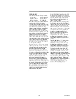
Mechanical Control Settings
The settings for the High Pressure
switch, Oil Pressure switch, and
Winding Thermostat are shown below:
CLOSE
OPEN
Compressor
300 ±20
405 ±7
Discharge
High Pressure
Switch - PSIG
Compressor Oil
47
50 ±3
Pressure Switch
-PSID
Compressor
181
221
Motor Winding
Thermostat - F
Domestic Water
115
130
Heater Solenoid
Thermostat - F
Diagnostics and
Troubleshooting
If no diagnostics exist, the selected
menu item will be displayed
continuously. When a diagnostic
occurs, the display will switch to the
Menu “0” and, depending on the
nature of the diagnostic, will do one of
the following:
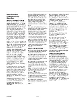
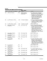
1. The display will “alternate” between
the Operating Code “A” at the time
of failure and the Diagnostic Code
“C” for any condition that causes the
entire shutdown (MMR and MAR
diagnostics). The display will
alternate between “A XX” and “C
YY”, where YY is the MMR or MAR
diagnostic that caused the machine
to shutdown. If multiple MMR or
MAR diagnostics occur, YY will be
the active diagnostic with the
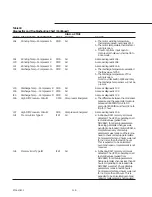
greatest priority. Priority, from the
highest to lowest, shall be as follows:
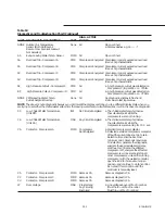
Cd
Contactor - Cprsr D (MMR)
CC
Contactor - Cprsr C (MMR)
Cb
Contactor - Cprsr B (MMR)
CA
Contactor - Cprsr A (MMR)
413
CPM module indicates EXV
module communications loss (MMR)
431
EXV Module indicates CPM
module communications loss (MMR)
Fd
Emergency Stop (MMR)
Ab
Evaporator Leaving Water
Temperature Sensor (MMR)
8E
Evaporator Entering Water
Temperature Sensor (MMR)
8A
Chilled Water Flow (Entering
Water Temperature) (MMR)
d8
Under Voltage (MAR)
d7
Over Voltage (MAR)
Ed
Chilled Water Flow Interlock
(MAR)
C6
Low Chilled Water Temp.
(Unit On) (MAR)
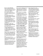
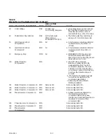
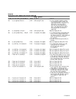
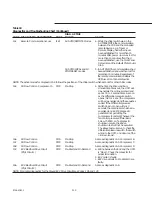
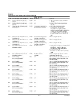
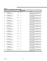
When multiple diagnostics exist and a
diagnostic with a higher priority is no
longer active, the diagnostic with lower
priority will replace it in the alternating
“A XX” and “C YY” displays.
Note:
MMR diagnostics only become
inactive after a RESET MAR diagnostics
become inactive when the condition
that caused them clears.
Содержание RTAA-130
Страница 2: ... American Standard Inc 1991 ...
Страница 8: ...8 RTAA IOM 3 ...
Страница 13: ...13 RTAA IOM 3 Figure 3 Typical RTAA Packaged Unit 240 400 Tons Control Panel Evaporator Outlet Inlet ...
Страница 24: ...24 RTAA IOM 3 ...
Страница 26: ...26 RTAA IOM 3 Figure 9 Dimensions and Clearances for RTAA Packaged Unit 130 to 200 Ton RTAA SU 1000E ...
Страница 27: ...27 RTAA IOM 3 Figure 10 Dimensions and Clearances for RTAA Packaged Unit 240 300 Ton RTAA SU 1001C ...
Страница 28: ...28 RTAA IOM 3 Figure 11 Dimensions and Clearances for RTAA Packaged Unit 340 to 400 Ton RTAA SU 1002C ...
Страница 38: ...38 RTAA IOM 3 RTAA SA 2002C Figure 19 Spring Isolator Placement for Typical RTAA Packaged Unit 240 400 Tons ...
Страница 46: ...46 RTAA IOM 3 Figure 24 Typical Domestic Water Heater Piping Figure 25 Typical Domestic Water Heater Piping ...
Страница 50: ...50 RTAA IOM 3 Figure 30 Refrigerant Circuit Identification ...
Страница 52: ...52 RTAA IOM 3 Figure 31 Remote Evaporator Piping Example ...
Страница 58: ...58 RTAA IOM 3 Continued on Next Page Figure 34 Typical Field Wiring for RTAA Packaged Unit 130 to 200 Tons ...
Страница 59: ...59 RTAA IOM 3 Continued from Previous Page See Notes on Next Page ...
Страница 61: ...61 RTAA IOM 3 Figure 35 Typical Field Wiring for RTAA Packaged Unit 240 400 Tons Continued on Next Page ...
Страница 63: ...63 RTAA IOM 3 Continued from Previous Page See Notes on Page 61 ...
Страница 64: ...64 RTAA IOM 3 Figure 36 Typical Field Wiring for RTAA With Remote Evaporator Option Continued on Next Page ...
Страница 65: ...65 RTAA IOM 3 Continued from Previous Page See Notes on Page 61 ...
Страница 76: ...76 RTAA IOM 3 ...
Страница 78: ...78 RTAA IOM 3 Figure 40 Refrigeration System and Control Components Single Circuit Continued on Next Page ...
Страница 80: ...80 RTAA IOM 3 Figure 41 Refrigeration System and Control Components Duplex Circuit Continued on Next Page ...
Страница 92: ...92 RTAA IOM 3 Figure 51 Operator Interface Controls ...
Страница 120: ...120 RTAA IOM 3 ...
Страница 126: ...126 RTAA IOM 3 Figure 56 Unit Sequence of Operation RTAA 240 to 400 Tons Continued on Next Page ...
Страница 127: ...127 RTAA IOM 3 Continued from Previous Page 2307 1566C ...
Страница 128: ...128 RTAA IOM 3 Figure 57 Unit Sequence of Operation RTAA 130 to 200 Tons 2306 9122A ...
Страница 132: ...132 RTAA IOM 3 Figure 58 Operator s Log ...
Страница 138: ...138 RTAA IOM 3 ...

