105
RTAA-IOM-3
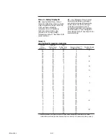
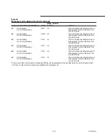
Table 17
Compressor(s) Current Limit Setpoint vs Chiller Current Limit
Setpoint (CLS)
Number of Compressors on a Unit
Two (130-215)
Three (240-300)
Four (340-400)
Number of
Number of
Number of
compressors
compressors
compressors
System
in operation
in operation
in operation
CLS
One
Two
One
Two
Three
One
Two
Three
Four
120%
120
120
120
120
120
120
120
120
120
100%
120
100
120
120
100
120
120
120
100
80%
120
80
120
120
80
120
120
107
80
60%
120
60
120
90
60
120
120
80
60
40%
80
40
120
60
40
120
80
53
40
Operational Features
Entering Evaporator Water
Temperature
When one or more compressors are
running, the UCM continually monitors
and compares the entering and leaving
evaporator water temperatures. If the
temperature of the entering water
drops more than 2 F below the leaving
water temperature for more than 100
degree F seconds, the UCM uses this to
indicate a loss of water flow through
the evaporator, will shut down the
chiller and will display an MMR
diagnostic. See Figure 53.
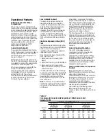
Current Limit Setpoint
The current limit setpoint (CLS) for the
chiller (front panel or remote) is entered
through the UCM menu. The current
limit setpoint for each compressor is
shown in Table 17.
Based upon current levels received at
the UCM, the compressor slide valve is
modulated to prevent the actual chiller
current from exceeding the CLS.
When a compressor is turned off, the
CLS for the remaining running
compressors shall be reset upward
immediately. When a compressor is
added, the CLS for the running
compressors shall ramped downward
at a rate not less than 10% RLA per
minute to the new setpoint.
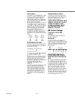
Low Ambient Lockout
The lockout provides a method for
preventing unit start-up when the
outdoor air temperature is below the
setpoint. If the outdoor temperature
goes below the setpoint during
operation, the UCM will go through a
normal shutdown of the unit. If the
outdoor temperature subsequently
increases to 5 F above the setpoint, the
UCM will automatically re-enable the
unit.
Electronic Expansion Valve (EXV)
Test
This test can be performed only when
the chiller switch is in the STOP/RESET
position. It will confirm proper
operation of the electronic expansion
valve and the EXV module.
Once the test has been initiated at the
UCM, the UCM will:
1. Overdrive the EXV closed (1250
steps)
2. Overdrive the EXV open (1250 steps)
3. Overdrive the EXV closed (1250
steps) 4. Reset the display to disable
and end the test
The EXV produces an audible clicking
sound only when it is driven against its
end stops. Step 1 drives the EXV to its
closed position, during which time
service personnel can move from the
UCM to the EXV.
Note:
A tool may be needed to aid in
hearing the clicking of the EXV, such as
a screwdriver held between the EXV
and the ear.
When Step 1 completes, the clicking
stops and the UCM begins to open the
EXV. When the EXV is fully opened, the
valve will begin to click against its end
stop. The service personnel must be
prepared to time the period between
the end of clicking in Step 1 and the
beginning of clicking in Step 2.
The time between the end of clicking in
Step 2 and the beginning of clicking in
Step 3 must also be recorded. The time
for the EXV to go from fully closed to
fully open should be approximately 15
seconds and the time to go back to
fully closed is approximately 15
seconds.
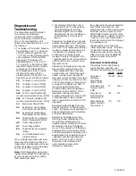
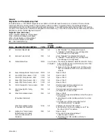
Current Overload Protection
The UCM continually monitors
compressor current to provide unit
protection in the event of an
overcurrent or locked rotor condition.
Protection is based on the phase with
the highest current and, if limits are
exceeded, the UCM will shutdown the
compressor and will display an CMR
diagnostic. See Figure 53.
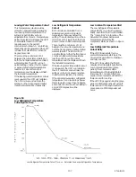
Leaving Chilled Water Temperature
Control
If the chiller switch is in the AUTO
REMOTE position and a remote chilled
water setpoint has been
communicated, the UCM will control to
that setpoint. Otherwise, it will control
to the front panel setpoint. Control is
accomplished by both staging
compressors and modulating the slide
valves on each compressor.
Upon start-up, if the leaving water
temperature is dropping 1.5 F per
minute or faster, the chiller will not load
further.
Содержание RTAA-130
Страница 2: ... American Standard Inc 1991 ...
Страница 8: ...8 RTAA IOM 3 ...
Страница 13: ...13 RTAA IOM 3 Figure 3 Typical RTAA Packaged Unit 240 400 Tons Control Panel Evaporator Outlet Inlet ...
Страница 24: ...24 RTAA IOM 3 ...
Страница 26: ...26 RTAA IOM 3 Figure 9 Dimensions and Clearances for RTAA Packaged Unit 130 to 200 Ton RTAA SU 1000E ...
Страница 27: ...27 RTAA IOM 3 Figure 10 Dimensions and Clearances for RTAA Packaged Unit 240 300 Ton RTAA SU 1001C ...
Страница 28: ...28 RTAA IOM 3 Figure 11 Dimensions and Clearances for RTAA Packaged Unit 340 to 400 Ton RTAA SU 1002C ...
Страница 38: ...38 RTAA IOM 3 RTAA SA 2002C Figure 19 Spring Isolator Placement for Typical RTAA Packaged Unit 240 400 Tons ...
Страница 46: ...46 RTAA IOM 3 Figure 24 Typical Domestic Water Heater Piping Figure 25 Typical Domestic Water Heater Piping ...
Страница 50: ...50 RTAA IOM 3 Figure 30 Refrigerant Circuit Identification ...
Страница 52: ...52 RTAA IOM 3 Figure 31 Remote Evaporator Piping Example ...
Страница 58: ...58 RTAA IOM 3 Continued on Next Page Figure 34 Typical Field Wiring for RTAA Packaged Unit 130 to 200 Tons ...
Страница 59: ...59 RTAA IOM 3 Continued from Previous Page See Notes on Next Page ...
Страница 61: ...61 RTAA IOM 3 Figure 35 Typical Field Wiring for RTAA Packaged Unit 240 400 Tons Continued on Next Page ...
Страница 63: ...63 RTAA IOM 3 Continued from Previous Page See Notes on Page 61 ...
Страница 64: ...64 RTAA IOM 3 Figure 36 Typical Field Wiring for RTAA With Remote Evaporator Option Continued on Next Page ...
Страница 65: ...65 RTAA IOM 3 Continued from Previous Page See Notes on Page 61 ...
Страница 76: ...76 RTAA IOM 3 ...
Страница 78: ...78 RTAA IOM 3 Figure 40 Refrigeration System and Control Components Single Circuit Continued on Next Page ...
Страница 80: ...80 RTAA IOM 3 Figure 41 Refrigeration System and Control Components Duplex Circuit Continued on Next Page ...
Страница 92: ...92 RTAA IOM 3 Figure 51 Operator Interface Controls ...
Страница 120: ...120 RTAA IOM 3 ...
Страница 126: ...126 RTAA IOM 3 Figure 56 Unit Sequence of Operation RTAA 240 to 400 Tons Continued on Next Page ...
Страница 127: ...127 RTAA IOM 3 Continued from Previous Page 2307 1566C ...
Страница 128: ...128 RTAA IOM 3 Figure 57 Unit Sequence of Operation RTAA 130 to 200 Tons 2306 9122A ...
Страница 132: ...132 RTAA IOM 3 Figure 58 Operator s Log ...
Страница 138: ...138 RTAA IOM 3 ...

