51
RTAA-IOM-3
Table 4
Liquid Line Size for Horizontal and/or Downflow Lines
Circuit Size:
Liquid Line Size (OD”)
Total Equiv. Length (Ft)
100 Ton
85 Ton
70 Ton
25'
1 1/8
1 1/8
1 1/8
50'
1 3/8
1 1/8
1 1/8
75'
1 3/8
1 3/8
1 3/8
100'
1 3/8
1 3/8
1 3/8
125'
1 3/8
1 3/8
1 3/8
150'
1 5/8
1 3/8
1 3/8
175'
1 5/8
1 5/8
1 5/8
200'
1 5/8
1 5/8
1 5/8
225'
1 5/8
1 5/8
1 5/8
250'
1 5/8
1 5/8
1 5/8
275'
1 5/8
1 5/8
1 5/8
300':
1 5/8
1 5/8
1 5/8
Table 5
Equivalent Lengths of Non-Ferrous valves and Fittings
Line Size
Globe
Angle
Short
Long
Inches OD
Valve
Valve
Radius ELL
Radius ELL
1 1/8
87
29
2.7
1.9
1 3/8
102
33
3.2
2.2
1 5 /8
115
34
3.8
2.6
2 1/8
141
39
5.2
3.4
2 5/8
159
44
6.5
4.2
3 1/8
185
53
8.0
5.1
3 5/8
216
66
10.0
6.3
4 1/8
248
76
12.0
7.3
Reproduced by permission of Air conditioning and Refrigeration Institute.
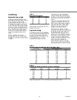
Line Sizing
Equivalent Line Length
To determine the appropriate size for
field installed liquid and suction lines, it
is first necessary to establish the
equivalent length of pipe for each line.
An initial approximation can be made
by assuming that the equivalent length
of pipe is 1.5 times the actual length of
pipe. These assumed lengths can then
be used with the appropriate tables in
the Liquid Line Sizing section and the
Suction Line Sizing sections which
follow.
It is also necessary to know the
capacity (tons) of each circuit. Circuit
capacities for each RTAA unit are listed
in Table 3.
The following are examples of how to
determine line sizes.
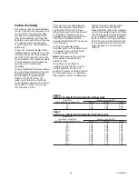
Liquid Line Sizing
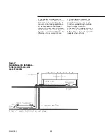
This example uses the unit installation
shown in Figure 31 and assumes an 85
ton circuit. The actual length of field
installed piping is 117 feet (80 + 8 + 8 +
21). Using the factor of 1.5, the
equivalent line length is 175 feet.
From Table 4, for horizontal and/or
downflow liquid lines, and assuming
an 85 ton circuit, 175 feet of equivalent
line requires a liquid line with an OD of
1 5/8 in.
There are 6 long-radius elbows in this
example. Using Table 5 and the pipe
OD of 1 5/8 in., these fittings represent
15.6 feet (6 elbows @ 2.6 feet each).
Therefore our new equivalent line
length is 132.6 feet (117 +15.6).
Referring back to Table 4, an 85 ton
circuit with 132.6 feet of equivalent pipe
length (use the dimension closest to
the calculated dimension) can use a
pipe O.D. of 1% in. rather than 1 5/8 in.
From Table 5 we see that the 6 elbows
of 1 3/8 in. have an equivalent pipe
length of 13.2 feet (6 elbows @ 2.2 feet
each). This further reduces the
equivalent pipe length to 130.2 feet
(117 + 13.2), and, as shown in Table 4,
still allows the use of 1 3/8 in. O.D. pipe.
Table 3
RTAA Circuit Capacities
Model
Circuit 1
Circuit 2
130
70
70
140
70
70
155
85
70
170
100
70
185
100
85
200
100
100
Содержание RTAA-130
Страница 2: ... American Standard Inc 1991 ...
Страница 8: ...8 RTAA IOM 3 ...
Страница 13: ...13 RTAA IOM 3 Figure 3 Typical RTAA Packaged Unit 240 400 Tons Control Panel Evaporator Outlet Inlet ...
Страница 24: ...24 RTAA IOM 3 ...
Страница 26: ...26 RTAA IOM 3 Figure 9 Dimensions and Clearances for RTAA Packaged Unit 130 to 200 Ton RTAA SU 1000E ...
Страница 27: ...27 RTAA IOM 3 Figure 10 Dimensions and Clearances for RTAA Packaged Unit 240 300 Ton RTAA SU 1001C ...
Страница 28: ...28 RTAA IOM 3 Figure 11 Dimensions and Clearances for RTAA Packaged Unit 340 to 400 Ton RTAA SU 1002C ...
Страница 38: ...38 RTAA IOM 3 RTAA SA 2002C Figure 19 Spring Isolator Placement for Typical RTAA Packaged Unit 240 400 Tons ...
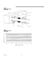
Страница 46: ...46 RTAA IOM 3 Figure 24 Typical Domestic Water Heater Piping Figure 25 Typical Domestic Water Heater Piping ...
Страница 50: ...50 RTAA IOM 3 Figure 30 Refrigerant Circuit Identification ...
Страница 52: ...52 RTAA IOM 3 Figure 31 Remote Evaporator Piping Example ...
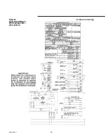
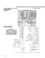
Страница 58: ...58 RTAA IOM 3 Continued on Next Page Figure 34 Typical Field Wiring for RTAA Packaged Unit 130 to 200 Tons ...
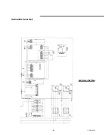
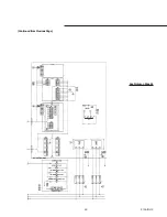
Страница 59: ...59 RTAA IOM 3 Continued from Previous Page See Notes on Next Page ...
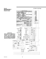
Страница 61: ...61 RTAA IOM 3 Figure 35 Typical Field Wiring for RTAA Packaged Unit 240 400 Tons Continued on Next Page ...
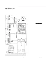
Страница 63: ...63 RTAA IOM 3 Continued from Previous Page See Notes on Page 61 ...
Страница 64: ...64 RTAA IOM 3 Figure 36 Typical Field Wiring for RTAA With Remote Evaporator Option Continued on Next Page ...
Страница 65: ...65 RTAA IOM 3 Continued from Previous Page See Notes on Page 61 ...
Страница 76: ...76 RTAA IOM 3 ...
Страница 78: ...78 RTAA IOM 3 Figure 40 Refrigeration System and Control Components Single Circuit Continued on Next Page ...
Страница 80: ...80 RTAA IOM 3 Figure 41 Refrigeration System and Control Components Duplex Circuit Continued on Next Page ...
Страница 92: ...92 RTAA IOM 3 Figure 51 Operator Interface Controls ...
Страница 120: ...120 RTAA IOM 3 ...
Страница 126: ...126 RTAA IOM 3 Figure 56 Unit Sequence of Operation RTAA 240 to 400 Tons Continued on Next Page ...
Страница 127: ...127 RTAA IOM 3 Continued from Previous Page 2307 1566C ...
Страница 128: ...128 RTAA IOM 3 Figure 57 Unit Sequence of Operation RTAA 130 to 200 Tons 2306 9122A ...
Страница 132: ...132 RTAA IOM 3 Figure 58 Operator s Log ...
Страница 138: ...138 RTAA IOM 3 ...

