background image

140

Installing, Removing, and Replacing

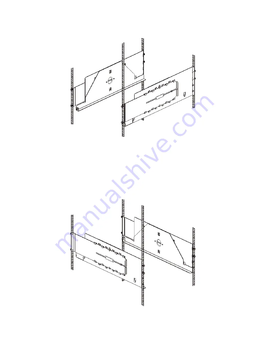
 a. Install the shelf’s rear studs in the rack’s rear mounting holes.

 b. Position the shelf to the appropriate side of the rack (right or left) and align the shelf at the 

desired height. 

 c. Insert the shelf’s rear studs into the rack’s rear mounting holes. 

 d. Fasten a thumbnut to the end of each stud. Secure the rack tightly, so that the ferrule fits snugly 

within the hole in the rack.

 e. Next, install the shelf’s front studs in the rack’s front mounting holes.

Содержание Storage Library T128

Страница 1: ...USER S GUIDE 433568 01 ...

Страница 2: ...ication Published July 2006 Part No 433568 01 ADIC P N 6 01710 01 Rev A International headquarters Worldwide subsidiaries Tandberg Data ASA Kjelsåsveien 161 Oslo P O Box 134 Kjelsås N 0411 Oslo Norway Tel 47 22 18 90 90 Fax 47 22 18 95 50 www tandberg com Tandberg Data Corp 12860 Danielson Court Poway CA 92064 U S A Tel 1 858 726 1800 Fax 1 858 726 1801 Tandberg Data GmbH Feldstrasse 81 D 44141 Do...

Страница 3: ...bility 5 Unused Storage Slots 6 Front Panel Components 6 Access Door 6 I E Station 7 Operator Panel 7 Front Power Switch 7 Back Panel Components 7 Rear Power Switches 8 Power System 8 Library Control Blade 10 Robotic System and Barcode Scanner 11 Tape Drive Support 12 Library Features 12 Licensable Features 12 Capacity On Demand COD 13 Partitions 14 Logical Unit Numbering LUN 14 User Interface 14 ...

Страница 4: ...ation 32 Configuring Network Settings 33 Working With Partitions 34 Automatically Creating Partitions 35 Manually Creating Partitions 35 Modifying Partitions 36 Deleting Partitions 37 Deleting Partitions Before Permanently Removing Expansion Modules 37 Changing Partition Access 38 Changing Partition Modes 38 Configuring Cleaning Slots 39 Configuring I E Station Slots 40 Configuring Zero I E Statio...

Страница 5: ...rming Media Operations 57 Importing Media 58 Bulkloading 59 Moving Media 60 Exporting Media 60 Loading Tape Drives 61 Unloading Tape Drives 62 Changing the Tape Drive Mode 63 About Cleaning Tape Drives 63 Enabling AutoClean 64 Importing Cleaning Media 64 Exporting Cleaning Media 65 Manually Cleaning Tape Drives 66 Locking and Unlocking the I E Stations 66 Shutting Down or Restarting the Library 67...

Страница 6: ... to Permanently Remove the 9U Expansion Module 107 Removing the 9U Expansion Module 109 Preparing to Use the New Library Configuration 112 Replacing the 5U Library Control Module 115 Preparing to Remove the 5U Control Module 115 Removing the 5U Control Module 117 Replacing the 5U Control Module 120 Preparing to Use the 5U Control Module 122 Replacing a 9U Expansion Module 123 Preparing to Remove t...

Страница 7: ...g the Internal Network 157 Interpreting LEDs 158 LCB LEDs 158 Amber LED on the LCB 158 Servicing the LCB Based on LED Status 159 Tape Drive LEDs 159 Fibre Port Link LED on Tape Drives 160 Power Supply LEDs 161 11 Working With Cartridges and Barcodes 163 Handling Cartridges Properly 163 Write Protecting Cartridges 164 Barcode Requirements 164 Installing Barcode Labels 165 12 Specifications 167 Libr...

Страница 8: ...viii Contents ...

Страница 9: ...on 44 Table 8 Cover Plate Location 92 Table 9 Cover Plate Location after Removing a 9U Expansion Module 112 Table 10 Library Control Blade LEDs 158 Table 11 Amber LED on the Library Control Blade 159 Table 12 Tape Drive Activity 160 Table 13 Fibre Port Link LED on Tape Drive 160 Table 14 Power Supply LEDs 161 Table 15 Library Specification Summary 167 Table 16 Library Capacity 168 Table 17 Library...

Страница 10: ...x Tables ...

Страница 11: ...ack Panel Components 8 Figure 6 Power System LEDs 10 Figure 7 Library Control Blade LEDs 11 Figure 8 Operator Panel User Interface 22 Figure 9 Web Client User Interface 22 Figure 10 Library Location Coordinates 56 Figure 11 Stand Alone 5U Control Module SCSI Cabling 85 Figure 12 Multi Module SCSI Cabling 85 Figure 13 Stand Alone 5U Control Module Fibre Channel Cabling 87 Figure 14 Multi Module Fib...

Страница 12: ...xii Figures ...

Страница 13: ... held liable for damage arising from unauthorized use of the product The user assumes all risk in this aspect This unit is engineered and manufactured to meet all safety and regulatory requirements Be aware that improper use may result in bodily injury damage to the equipment or interference with other equipment Product Model Number The StorageLibrary model number is as follows i500 Explanation of...

Страница 14: ...nd in the product box or at www tandberg com Tandberg StorageLibrary 128 Quick Start Guide 433567 xx System Safety and Regulatory Information Guide 433605 xx Getting More Information or Help Please visit www tandberg com for information about how to contact Tandberg Data Note Indicates important information that helps you make better use of your system ...

Страница 15: ...lable performance and storage capacity The Tandberg StorageLibrary T128 library is designed for ease of installation configuration and field upgrades The Tandberg StorageLibrary T128 library is built upon two basic building blocks the 5U control module and 9U expansion module where 1U 1 75 These building blocks form the basis of the following available library configurations A 5U library consistin...

Страница 16: ...ave a stand alone 5U control module you can add a 9U expansion module to increase the size of your library to 14U See Figure 3 on page 5 for an illustration of library scalability Table 1 shows the specifications for the available library configurations Each module has a specific number of fixed storage slots I E station slots and tape drive slots available See Table on page 168 for more informati...

Страница 17: ...ontains only cartridges all power is derived from the control module Stackability The two base systems for the Tandberg StorageLibrary T128 are the 5U library consisting of a 5U stand alone control module and the 14U library consisting of a 5U control module and a 9U expansion module In addition a 9U expansion module can be added to an existing 5U library to expand the size of the library to 14U w...

Страница 18: ...Panel Components The Tandberg StorageLibrary T128 library is made up of physical hardware components Figure 4 on page 6 shows the front panel components of the library The paragraphs following Figure 4 describe the components in detail Figure 4 Front Panel Components Access Door The access door allows access to the internal components of the library Each control module and expansion module has an ...

Страница 19: ...ome part of a logical division of library resources known as a partition The I E station is shared among all partitions but the I E station slots are owned by one partition at a time When an I E station slot is assigned to a partition only that partition can access that slot Operator Panel The operator panel is the touch screen display device upon which the graphical user interface GUI appears The...

Страница 20: ...n has dual AC line input and dual DC power supplies If you have redundant power supplies you can hot swap a power supply power to the library remains on while you exchange the hardware and you can hot add power supplies to other modules power to the library remains on while you are adding the hardware WARNING TURN OFF THE REAR POWER SWITCH WHENEVER YOU ARE SERVICING THE LIBRARY IN THE EVENT OF DAN...

Страница 21: ...0 shows the power system LEDs For more information on the behavior of the LEDs see Power Supply LEDs on page 161 WARNING THE POWER OUTLET MUST BE AVAILABLE NEAR THE LIBRARY AND MUST BE EASILY ACCESSIBLE CAUTION The control module and each expansion module that contains drives must have at least one power supply for every four drives You can add a redundant power supply to each module Installing on...

Страница 22: ... is functioning properly The LCB indicates its status with three LED Reliability Availability and Serviceability RAS status indicators These indicators are green amber and blue in color Green represents processor status Amber represents health status Blue represents power control status Figure 7 on page 11 shows the location of the LCB components including LEDs For more information on the behavior...

Страница 23: ...he barcode scanner reads during the inventory process During the inventory process the barcode scanner reads the fiducial labels to identify the types of magazines and tape drives that are installed in the library Every tape cartridge must have a unique machine readable barcode attached to it Tape cartridges cannot have duplicate barcode labels This barcode identifies the cartridge The library sto...

Страница 24: ...Tape drives are installed into tape drive slots in the rear of the library If a tape drive slot is empty a filler plate covers the empty tape drive slots to prevent debris from entering the library Tape drives are shipped filling the tape drive slots from the bottom to the top of the library but the tape drives can be reinstalled in any available tape drive slot For information on adding tape driv...

Страница 25: ...n about your library configuration If you must replace your LCB flash card you will need to request a replacement license key from Tandberg Data Capacity On Demand COD The library ships with a minimum of 36 active slots At any time the COD feature allows you to enable the inactive storage slots within a library by using COD license keys COD license keys are available in 46 slot increments For info...

Страница 26: ...tor panel is located on the front door of the control module and allows users to work locally on the library via the user interface The web client interface allows users to view and perform library functions from remote sites and is accessible through a browser The operator panel and web client interface contain a similar user interface and functionality See Understanding the User Interface on pag...

Страница 27: ...eLibrary T128 User s Guide 15 System Requirements The Tandberg StorageLibrary T128 web client interface supports the following browsers Microsoft Internet Explorer version 6 0 and above Firefox version 1 0 6 and above ...

Страница 28: ...16 Description ...

Страница 29: ...nspecting 1 Unpack the library Following the unpacking instructions that came with the library remove the library exterior packaging but leave the library in the bottom packaging tray 2 Check the contents of the package against the packing slip 3 Remove the interior packaging After you have removed the packaging sleeve and while the library is still sitting in the bottom packaging tray remove all ...

Страница 30: ...uide for more information on finding an optimal location for your library Details on positioning the library include Make sure a power source only of the type marked on the product label is available See Specifications on page 167 for power requirements Route any cables to avoid walking on them or pinching them with items placed on or against them Pay particular attention to the cord at the wall r...

Страница 31: ... data path communications and network cables Two sets of cabling instructions are provided one for SCSI tape drives and one for Fibre Channel FC tape drives A library can have both SCSI and FC drives For cabling instructions see Cabling the Library on page 84 or the Quick Start Guide 6 Turn on power to the library Press the power switch on the front of the library once 7 Configure the library Conf...

Страница 32: ...ottom of the library for the robotic picker For instructions on importing tape cartridges see Importing Media on page 58 For information on bulkloading see Bulkloading on page 59 For complete installation instructions see Installing Removing and Replacing on page 83 9 Connect to the host application Set up the connection to the library host application If your host application inventories the loca...

Страница 33: ... the Tandberg StorageLibrary T128 Internet Protocol IP address to the list of trusted allowed sites on your Tandberg StorageLibrary T128 supported browser so the web client pages will automatically refresh Common User Interface Elements The user interface consists of four areas Header appears on every screen and contains the company logo product name and the three main navigation buttons The main ...

Страница 34: ...22 Understanding the User Interface Figure 8 Operator Panel User Interface Figure 9 Web Client User Interface ...

Страница 35: ... Tickets screen by selecting Tools All RAS Tickets See Troubleshooting on page 153 for more information about RAS tickets Home Page The home page is common to both the operator panel and the web client interface From the home page there are two modes of navigation to access the user interface screens tabs on the Capacity View and categorized function links on the Library View Capacity View The Cap...

Страница 36: ...ry s initial network configuration from the operator panel touch screen See Managing the Network on page 50 for information on setting the network configuration settings for remote use Menu Trees The following four menus organize commands into logical groupings The Setup menu consists of commands that you can use to set up and configure various aspects of the library including partitions I E stati...

Страница 37: ...uration Cleaning Slots Partitions Change Mode Save Restore Configuration Network Settings I E Station Slots Drive Load Unload Change Mode Identify Drives Logged in Users Drive IDs I E Station Lock Unlock Drive Operations All Slots Control Path System Shutdown Update Library Firmware About Tandberg StorageLibrary T128 License Log Out Notification Setup E mail Account Contact Information Users Date ...

Страница 38: ...ffect the physical library such as creating or deleting partitions A service user has access to the entire physical library and all of its partitions as well as to a hidden Service menu that includes service and diagnostic tools Each library has only one service user account Details on user privileges include The library can contain a maximum of eighteen user accounts user or administrative or bot...

Страница 39: ...ative privileges can change this to a value from 15 minutes to 480 minutes eight hours See Configuring System Settings on page 53 When a service user logs in all other active users are automatically logged out User Access See Table 3 on page 25 for the web client menu tree and privilege level information See Table 4 on page 25 for the operator panel menu tree and privilege level information ...

Страница 40: ...28 Understanding the User Interface ...

Страница 41: ...e web client The on screen instructions recommend that you choose to complete the wizard on the web client The web client Setup Wizard offers more options While completing the Setup Wizard remotely is recommended you may need to begin using the library locally immediately In this case you can complete the Setup Wizard on the operator panel or even cancel out of the Setup Wizard and allow the libra...

Страница 42: ...s to open the appropriate screens on both the operator panel and the web client are given for each task For the operator panel the paths refer to the navigation tabs at the top of the home page For the web client the paths refer to the menus For the menu trees on both the operator panel and web client see Menu Trees on page 24 Using the Setup Wizard The Setup Wizard simplifies the process of confi...

Страница 43: ...odify network and other settings The default configuration settings are as follows License keys 36 slots minimum The total number depends on number of pre activated slots purchased Network settings DHCP enabled Import export I E station slots 6 Cleaning cartridge slots 0 Partitions The default is one partition if your library contains only SCSI tape drives or only Fibre Channel FC tape drives If y...

Страница 44: ...face Local or Remote The Setup Wizard Local or Remote screens are parts of the operator panel Setup Wizard only Use the second Setup Wizard Local or Remote screen to select whether you want to finish configuring the library using the local operator panel or the remote web client The Web Client button is grayed out if the Internet Protocol IP address has not been configured The network configuratio...

Страница 45: ...fault Gateway text boxes unavailable Disable makes the IP Address Subnet Mask and Default Gateway text boxes available for you to manually set the library network settings IP Address is the IP address of the library This text box is available only if DHCP is disabled Default Gateway is the IP address of the default gateway for your portion of the Ethernet network This text box is available only if...

Страница 46: ...mber of existing partitions The maximum number of partitions that can be created is equal to the number of drives in the library Table 5 shows the possible number of partitions that can be created for each of the available library configurations Details on partitions include Administrative users can create modify delete and control access to all partitions Users can be given access to only certain...

Страница 47: ...fferent partitions To manually create partitions use the web client See Manually Creating Partitions on page 35 The paths to open the appropriate screens are as follows From the web client select Setup Partitions From the operator panel select Setup Create Partitions Manually Creating Partitions Using the web client administrative users can manually create additional partitions any time after the ...

Страница 48: ...control path is grayed out For more information on setting the control path see Modifying the Control Path on page 43 Also the library does not support mixing FC and SCSI tape drives in one partition Assign just one tape drive type to a given partition The library automatically takes the partition offline before modifying it and places the partition back online after it is modified When modifying ...

Страница 49: ...itions Before Permanently Removing Expansion Modules Because partitions extend across the library s physical modules and share resources the library will report errors if you permanently remove an expansion module from your library without first deleting partitions and modifying shared resources such as cleaning slots and I E slots See Removing 9U Expansion Modules From an Existing Library on page...

Страница 50: ...artitions to which the user has access The paths to open the appropriate screens are as follows From the web client select Setup Users From the operator panel select Setup Modify Users Changing Partition Modes This topic focuses on using the library user interface not the host application to change partition mode Changing a partition mode using the library user interface may affect your host appli...

Страница 51: ...otifies the library If AutoClean is enabled the library automatically cleans the tape drive using a cleaning cartridge loaded in a cleaning slot Cleaning slots are not assigned to specific partitions They are shared by all partitions within a library Each partition can access cleaning cartridges located in the dedicated cleaning slots The maximum number of cleaning slots that can be configured is ...

Страница 52: ...rol module with six I E station slots and a 9U expansion module with 12 station slots All 12 of the slots in the 9U expansion module must be configured the same way as either I E station slots or storage slots Therefore a 14U library can contain a minimum of six and a maximum of 18 dedicated I E station slots Table 6 on page 41 lists the number of I E station slots available per library for all ba...

Страница 53: ... the Reports menu See Viewing the Library Configuration on page 69 Configuring Zero I E Station Slots Configuring zero I E slots increases the number of storage slots in your library but has the following consequences You will not be able to use the I E station to import and export tape cartridges including cleaning media You will be required to open the library access door to bulkload and unload ...

Страница 54: ...ives 5U control module 1 and 2 9U expansion module 3 4 5 and 6 For FC tape drives The loop ID can be set to a value between 0 125 A unique loop ID is selected by default for all FC tape drives installed in the library For example the tape drive installed in the top drive bay of a 5U control module is assigned a default loop ID of 61 The tape drive installed in the 5U control module s bottom drive ...

Страница 55: ... is designated the control path In the event that the control path connection to the host application fails you can select a new control path for the partition After you modify the control path the library will reset the tape drive by changing the drive mode from online to offline and then back to online The paths to open the appropriate screens are as follows From the web client select Setup Cont...

Страница 56: ...open the appropriate screens are as follows From the web client select Setup License From the operator panel select Setup Licenses Obtaining a Capacity On Demand License Key All Tandberg StorageLibrary T128 library configurations ship with the purchased number of slots pre activated The number of available pre activated slots begins at 36 for all library configurations and increases in 46 slot inc...

Страница 57: ... your library control blade LCB compact flash card The LCB compact flash card contains information about your library configuration including licensed features For contact information see Getting More Information or Help on page 2 To obtain your COD license key for a COD slot upgrade 1 Contact your Tandberg Data technical sales representative to submit your order for a COD slot upgrade You can pur...

Страница 58: ...llows From the web client select Setup Notification Contact Information From the operator panel select Setup Notification Configuring the Library E mail Account The library uses the library e mail account whenever library e mail services are used such as when the library automatically sends e mail notifications about library issues The Setup E mail Account screen contains the following fields SMTP...

Страница 59: ...strative users can configure the library e mail account and e mail notifications Users can receive e mail notifications but they cannot configure the library e mail account and or notifications You can configure e mail notifications from the web client user interface only but you can view them from the operator panel user interface The paths to open the appropriate screens are as follows From the ...

Страница 60: ...er account The user name for this account is admin and the password is password You cannot delete this user account or change the user name but you can change the password The default administrative user account is used to perform the initial configuration of the library If you misplace the password for the default administrative account contact Technical Support For contact information see Gettin...

Страница 61: ...name Instead you will need to delete the user account and create a new one To modify user accounts you need to provide information for the following fields Password the unique password for the user account you are creating Passwords are limited to 6 12 lower case alphanumeric characters and can include dashes underscores and at symbols for example pass_ 1 2 3 Privilege Level set to either User or ...

Страница 62: ...lect Setup Date Time Managing the Network The Network Management screens contain three tabs SSL Trap Registration SNMP Version Administrative users can use the operator panel to modify the network management settings at any time The network management settings cannot be set on the web client but the settings are viewable in a read only format under the Reports menu Note The library automatically a...

Страница 63: ...ears at the top of the list Default Port number is 162 If no IP address is selected the Modify and Delete buttons are grayed out Modify IP address If an IP address is selected the Create button is grayed out Delete IP address If an IP address is selected the Create button is grayed out Note Selecting Apply on any one of the Network Management tabs SSL Trap Registration and SNMP Version applies the...

Страница 64: ...rk Interface enables or disables all external access to the library This setting is enabled by default to allow external access SSH Services enable or disable Secure Shell SSH services such as SSH port 22 from accessing the library This setting is enabled by default ICMP enables or disables external attempts to discover the library by pinging it by means of the Internet Control Message Protocol IC...

Страница 65: ...erator panel The beep sound can be disabled or enabled at any time by selecting the Touch screen audio enable checkbox User session timeout minutes The library automatically logs out a user or administrative user when the library has detected no activity for 30 minutes You can adjust the user session time by entering a numeric value in the User session timeout minutes text box Valid user session t...

Страница 66: ...st settings The current applied settings appear on the screen The brightness and contrast settings can be adjusted The Defaults button sets the brightness and contrast to the default settings You cannot configure the display settings from the web client The path to open the appropriate screen is as follows From the operator panel select Tools Display Settings Registering the Library Registering th...

Страница 67: ...numeric characters and can include dashes underscores _ and at symbols for example pass_ 1 2 3 For information on changing passwords see Modifying User Accounts on page 49 Logging Out Logging out secures the library from being accessed by unauthorized users Log out whenever you have finished accessing the library through either the web client or the operator panel From the web client or the operat...

Страница 68: ...o the control module The control module is numbered 0 zero Expansion modules stacked above the control module are addressed with positive integer digits depending on their position above the control module For example the expansion module stacked directly above the control module is number 1 The expansion module stacked directly above module 1 is number 2 and so on Modules stacked below the contro...

Страница 69: ... Supplies Power supplies are addressed as module PS where PS is 1 for the left power supply and 2 for the right power supply The PS is also etched on the module chassis above each power supply Performing Media Operations Administrative users and users can use commands on the web client and operator panel Operations menu to perform the following media operations Import data cartridges into the libr...

Страница 70: ...ator panel to import cartridges The process for importing cartridges includes the following steps 1 Go to the front of the library and insert cartridges into the I E station 2 Close the I E station door The Assign IE screen appears on the operator panel You must assign the cartridges to a partition before the import operation can begin The screen lists only the partitions to which you have been gi...

Страница 71: ...ee Viewing the Library Configuration on page 69 When I E station slots have been configured as I E slots the I E station door is unlocked and you can open the main access door to the library When all I E station slots are configured as storage the I E station door is always locked You will not be able to open the main access door to bulkload tape cartridges into the library without first unlocking...

Страница 72: ...nformation in the user interface to move media Partition lists the partitions that you have permission to access Selected Media the single cartridge that you want to move Selected Destination the location to which you want to move the cartridge The paths to open the appropriate screens are as follows From the web client select Operations Media Move From the operator panel select Operations Move Me...

Страница 73: ...t is limited to the number of empty slots Media the tape cartridges that you want to export The paths to open the appropriate screens are as follows From the web client select Operations Media Export From the operator panel select Operations Export Media For step by step procedures see the library s online Help To access the online Help system click the Help icon at the top right of the web client...

Страница 74: ...media loaded appear on the screen You can select only partitions to which you have been given access If the affected partition is online it will be taken offline before the unload operation is performed and brought back online after it is complete You need to provide the following information in the Unload Drive screens to unload tape cartridges from tape drives Partition the partition containing ...

Страница 75: ...rtridges AutoClean and Manual AutoClean Configuring one or more dedicated cleaning slots automatically enables AutoClean Cleaning cartridges are stored in the designated cleaning slots When a tape drive needs cleaning it notifies the library and the library automatically cleans the tape drive using a cleaning cartridge loaded in a cleaning slot Automatic cleaning is integrated into routine library...

Страница 76: ...erator panel to import cleaning cartridges The process for importing cleaning cartridges includes the following steps 1 Go to the front of the library and insert the cartridges into the I E station 2 Close the I E station door The Assign IE screen appears on the operator panel 3 On the Assign IE screen select System The System button turns red after it is selected Selecting System assigns the cart...

Страница 77: ...e You must have access to the library s I E Station and the operator panel to export cleaning cartridges You can only export cartridges if empty I E station slots are available You need to provide the following information in the Export Cleaning Media screens to export cleaning media Media the tape cartridges that you want to export The screen includes information about the number of empty I E sta...

Страница 78: ...re finished accessing the I E station make sure the station door is fully closed Administrative users can use this operation to lock or unlock the doors for all I E stations that are configured as I E station slots If all I E station slots are configured as storage this operation unlocks the control module I E station only There are three reasons the I E station door locks The library imports or e...

Страница 79: ...wer from the library you must turn off the power switch on each power supply Power is completely removed from the library when the blue LED on each power supply turns off To turn the library back on turn the power switch on on each power supply press the front power switch again and then follow the login procedure Restart shuts down and restarts the library s operating system and firmware When per...

Страница 80: ...68 Running Your Library ...

Страница 81: ...L SN firmware level sled boot version and sled application version of all installed tape drives The path to open the report from the web client is Reports System Information Viewing the Library Configuration The Library Configuration report is a dynamic representation of the physical locations of various library resources including tape drives slots partitions and modules Use the report to view in...

Страница 82: ...library SNMP Traps IP addresses and ports of the library The path to open the report from the web client is Reports Network Settings Viewing Logged in Users The User Login report contains information about the users that are currently logged into the library The report contains the following information User name name of logged in user Role name privilege level of logged in user Admin for administ...

Страница 83: ...t From the web client you can view the About Tandberg StorageLibrary T128report which provides the following information about the library Serial Number Firmware Version Number From the operator panel you can navigate to the About screen which provides the following information about the library Library Name Serial Number Firmware Version Number Current Date Current Time From the About screen you ...

Страница 84: ...72 Getting Information ...

Страница 85: ... tape drive firmware using an image file is a lengthy process taking up to 90 minutes for each tape drive In addition you can create a Firmware Update FUP tape of a tape drive firmware version already installed in your library A FUP tape contains a specific version of tape drive firmware You can use the tape to transfer firmware to one or more tape drives installed in the library This chapter expl...

Страница 86: ... personal computer a On the Tandberg Data Support website navigate to your product s firmware b Select the appropriate firmware version and download the file to your computer hard drive 3 From the web client select Tools Update Library Firmware 4 Click Browse 5 Locate the firmware file that you have downloaded and click Open 6 Select Apply A dialog box appears informing you that the library will r...

Страница 87: ...ed onto the FUP tape which you can then use to update the drive firmware on all of the specified drives within the library Drive code versions are independent of the library versions The entire process of creating a FUP tape can be performed using the operator panel If you choose to create the tape using the web client be aware that part of the process must be performed on the operator panel and t...

Страница 88: ...Wait for the Assign I E screen to appear on the local operator panel The screen lists one or more partitions and the System button 6 On the Assign I E screen select System The System button turns red after it is selected Selecting System assigns the cartridge to the physical library and not to a specific partition 7 If you are using the operator panel to complete the process proceed to step 8 If y...

Страница 89: ...erform this operation If the tape drive you want to use contains a tape cartridge you will need to unload it first Erase a FUP tape using the following steps 1 If you are using the operator panel select Tools Drive Mgmt If you are using the web client select Tools Drive Operations A screen listing drive management operations appears 2 Select the option to erase a firmware tape 3 On the subsequent ...

Страница 90: ...site at www tandberg com provides information that can help you to verify that the library is running the appropriate level of tape drive firmware compatible with the tape drive type You cannot use a SCSI FUP tape to update tape drive firmware on a FC tape drive and vice versa Each tape drive interface type requires unique firmware See Creating a FUP Tape on page 75 for more information on FUP tap...

Страница 91: ...lient to complete the process select View I E Stations to verify that the scratch tape is in the top slot of the station Selecting View I E Stations opens the Library Configuration Report See Viewing the Library Configuration on page 69 for more information on this report 8 Select Apply The tape drive firmware update takes approximately three minutes The library moves the newly created FUP tape in...

Страница 92: ...ith the tape drive type Note that you cannot use a SCSI firmware image to update tape drive firmware on a FC tape drive and vice versa Each tape drive interface type requires unique firmware The library allows you to update firmware on multiple tape drives at one time Update firmware on all tape drives of the same interface type at the same time to make sure that all drives are at the same firmwar...

Страница 93: ...st a new FUP tape with updated tape drive firmware from technical support Go to www tandberg com and select your region You will be redirected to a regional Tandberg Data website providing contact information Submit a request for a new FUP tape When you receive the FUP tape you can use it to update your library s tape drives following the instructions in Using a FUP Tape to Update Tape Drive Firmw...

Страница 94: ...ss message notifies you when the update operation has completed successfully 6 When you see the Success message click OK A dialog box appears with information on where the log was saved in the library 7 Click OK A Save as dialog box appears 8 Use the dialog box to determine where you want to save the file and click OK For more detailed step by step instructions see your library s online Help To ac...

Страница 95: ...EARTHING GROUNDING TERMINAL AND POWER MUST BE SUPPLIED VIA AN INDUSTRIAL PLUG AND SOCKET OUTLET AND OR AN APPLIANCE COUPLER COMPLYING WITH IEC 60309 OR AN EQUIVALENT NATIONAL STANDARD AND HAVING A PROTECTIVE EARTH GROUND CONDUCTOR WITH A CROSS SECTIONAL AREA OF AT LEAST 1 5 MM2 14 AWG TO ENSURE PROPER AIRFLOW AND ACCESS SPACE ALLOW 60 CM 24 INCHES IN THE FRONT AND BACK OF THE LIBRARY WARNING UNDER...

Страница 96: ...R WITH A CROSS SECTIONAL AREA OF AT LEAST 1 5 MM2 14 AWG TO ENSURE PROPER AIRFLOW AND ACCESS SPACE ALLOW 60 CM 24 INCHES IN THE FRONT AND BACK OF THE LIBRARY Taking the Library Online Offline Taking a library online makes it accessible to host applications via the Storage Area Network SAN Taking a library offline makes it inaccessible to host applications via the SAN Taking a Library Online 1 Usin...

Страница 97: ... to hold modules if you want to install your library in a rack See Installing the Rackmount Kit on page 138 for instructions The instructions include procedures for removing and replacing tape drives 2 Connect the SCSI cables to the tape drives a Terminate the SCSI tape drive with an appropriate SCSI terminator b Connect the SCSI tape drive to the host ...

Страница 98: ...t the module to module cable from the control module to the 9U expansion module 4 Connect your Ethernet cable to the Gigabit GB Ethernet port on the library control blade LCB for remote access to the library via the web client 5 Connect a power cord to the outlet on the power supply on the rear of the library There should always be a power cord connected to the power supply on the control module I...

Страница 99: ...brary Cables Fibre Channel Use this procedure along with Figure 13 and Figure 14 on page 87 if you are installing a library that includes FC tape drives Figure 13 Stand Alone 5U Control Module Fibre Channel Cabling Figure 14 Multi Module Fibre Channel Cabling ...

Страница 100: ...ontrol module d Connect the module to module cable from the control module to the 9U expansion module 4 Connect your Ethernet cable to the Gigabit GB Ethernet port on the Library Control Blade LCB for remote access to the library via the web client 5 Connect a power cord to the outlet on the power supply on the rear of the library There should always be a power cord connected to the power supply o...

Страница 101: ...ss door and lift the control module and place it in the desired location 5 If you are placing the control module in a rack use the rack ears to fasten the control module to the rack 6 If not already installed install the library control blade LCB in the control module See Removing and Replacing the Library Control Blade and LCB Compact Flash Card on page 133 for instructions on installing the LCB ...

Страница 102: ...rol module a Open the I E station and access doors of each module b Using your hands gently lift the robot assembly into the control module The robot assembly should glide slowly and with some resistance c After raising the robot assembly to the approximate middle of the control module hold it in place with one hand and using your other hand swivel the parking tab toward you The metal parking tab ...

Страница 103: ...d Gently release the robot assembly to rest on the parking tab 5 Remove and replace the cover plates if appropriate CAUTION Before removing the control module s bottom cover plate the robot assembly must be parked as described in Step 4 on page 90 ...

Страница 104: ...er plate and the 9U expansion module s bottom plate Recommended location for adding an expansion module Installing the 9U Expansion Module 1 Open the 9U expansion module s access door and raise the guide pin by pulling it up and turning it slightly as if it were a screw Otherwise the guide pin may scratch the front doors of the module on which you are stacking Table 8 Cover Plate Location 5U 14U c...

Страница 105: ... two thumbscrews at the base of the front of the module and the two thumbscrews located at the base of the back of the module Then lower the module s guide pin located at the base of the front of the module by turning it and pushing it down 4 Tighten all thumbscrews located at the base of the front and back of the modules 5 Fasten the module to the rack with rack ears See Installing the Rackmount ...

Страница 106: ... and Replacing 6 If stacking the 9U expansion module on top of another module engage the Y rails of the new module in your library configuration Ensure that the Y rails are properly aligned and the thumbscrews are tightened ...

Страница 107: ...nd place it in the desired location 3 If stacking the control module on top of another module secure the two modules together by tightening the two thumbscrews at the base of the front of the module and the two thumbscrews located at the base of the back of the module Then lower the module s guide pin located at the base of the front of the module by turning it and pushing it down 4 Tighten all th...

Страница 108: ... the module When replaced correctly the parking tab will not accidentally swivel into the path of the robot c Gently release the robot assembly It will lower to the bottom module of the library 2 Close the library s I E station and access doors 3 Add the tape drives to the modules For details see Adding Removing and Replacing Tape Drives on page 148 CAUTION Support the robot assembly by holding on...

Страница 109: ...m These instructions explain how to add a 9U expansion module to an existing library There are some configuration settings to take into account when adding a 9U expansion module to an existing library All COD licenses remain the same If the current license key does not cover the expanded capacity you will need a new license key to use the newly available slots Partition I E station slot and cleani...

Страница 110: ... The robot assembly should glide slowly and with some resistance WARNING ALL LIBRARIES MAY BE INSTALLED IN A RACK HAVING A MAIN PROTECTIVE EARTHING GROUNDING TERMINAL AND POWER MUST BE SUPPLIED VIA AN INDUSTRIAL PLUG AND SOCKET OUTLET AND OR AN APPLIANCE COUPLER COMPLYING WITH IEC 60309 OR AN EQUIVALENT NATIONAL STANDARD AND HAVING A PROTECTIVE EARTH GROUND CONDUCTOR WITH A CROSS SECTIONAL AREA OF...

Страница 111: ...ease the robot assembly to rest on the parking tab 6 Remove all power supplies from each module 7 Remove all tape drives from each module Unstacking the Existing Modules 1 Starting with the topmost module of your library open the I E station and access doors 2 If your current configuration already uses a 9U expansion module disengage the Y rails so the modules can be safely unstacked CAUTION Befor...

Страница 112: ...place b From the rear of the library find the rear Y rail release mechanism located in the interior of the right side of the module Squeeze the handle of the Y rail release mechanism lift it and release it so that it locks into place 3 Remove the rack ears that fasten the module to the rack 4 Loosen the thumbscrews located at the base of the front and rear of the module Note The rear Y rail is imp...

Страница 113: ...ary T128 User s Guide 101 5 Open the module s access door and raise the guide pin by pulling it up and turning it slightly as if it were a screw Otherwise the guide pin may scratch the front doors of the module beneath it ...

Страница 114: ... plates if appropriate a If you plan to stack the 5U control module at the top of the library remove the control module s bottom cover plate and the 9U expansion module s top plate b If you plan to stack the 5U control module at the bottom of the library remove the control module s top cover plate and the 9U expansion module s bottom plate Recommended location for adding an expansion module CAUTIO...

Страница 115: ...the front of the library place it in the desired location 5 If there is already a module installed secure the two modules together by tightening the two thumbscrews at the base of the front of the module and the two thumbscrews located at the base of the back of the module Then lower the module s guide pin located at the base of the front of the module by turning it and pushing it down 6 Tighten a...

Страница 116: ...ened a From the front of the library open the I E station and access doors of the 9U expansion module Squeeze the handle of the Y rail release mechanism lift it out of its locked position and slide it downward as far as it will go From the back of the library find the rear Y rail release mechanism which is located in the interior of the right side of the module Squeeze the handle ...

Страница 117: ...the control module For details see Removing and Replacing the Library Control Blade and LCB Compact Flash Card on page 133 4 Unpark the robot assembly a Gently raise the robot assembly so that it no longer rests on the parking tab b With your free hand swivel the parking tab away from you until it is removed completely from the interior of the module When replaced correctly the parking tab will no...

Страница 118: ... of the stack of modules For cabling instructions see Cabling the Library on page 84 6 Power on the library 7 Reconfigure the library including applying the new COD license key using the operator panel or web client 8 Add the tape cartridges to the library s modules using the I E station commands from the operator panel or web client 9 Open the host application and reinventory in order to synchron...

Страница 119: ...for removing and replacing the top cover plate T10 TORX screwdriver for removing and replacing the bottom cover plate You need to unstack the 14U library to remove the 9U expansion module 1 Remove all tape cartridges from the library using the import and export commands of the operator panel or web client 2 Reconfigure the library with the following settings Partitions 0 Cleaning slots 0 WARNING A...

Страница 120: ...ol module The robot assembly should glide slowly and with some resistance c After raising the robot assembly to the approximate middle of the control module hold it in place with one hand and using your other hand swivel the parking tab toward you The metal parking tab is located at the bottom of column 1 d Gently release the robot assembly to rest on the parking tab 6 Remove all power supplies fr...

Страница 121: ...oving and Replacing Tape Drives on page 148 Removing the 9U Expansion Module 1 For each module that you plan to remove open the I E station and access doors of each module 2 Disengage the Y rails so the modules can be unstacked safely CAUTION Before unstacking the modules the robot assembly must be parked as described in Step 5 on page 108 ...

Страница 122: ...place b From the rear of the library find the rear Y rail release mechanism located in the interior of the right side of the module Squeeze the handle of the Y rail release mechanism lift it and release it so that it locks into place 3 Remove the rack ears that fasten the module to the rack See Installing the Rackmount Kit on page 138 for detailed instructions on using the rack ears 4 Loosen the t...

Страница 123: ...ew Otherwise the guide pin may scratch the front doors of the module beneath it 7 From the front of the library slide the entire module toward you and lift it off of the module below it 8 Repeat these procedures for each module that you intend to remove 9 Remove and replace the cover plates if appropriate CAUTION Before removing the control module s bottom cover plate the robot assembly must be pa...

Страница 124: ... If you plan to stack the 5U control module at the bottom of the library remove the control module s top cover plate and the 9U expansion module s bottom plate Preparing to Use the New Library Configuration 1 Ensure that the Y rails are properly aligned and the thumbscrews are tightened Table 9 Cover Plate Location after Removing a 9U Expansion Module 5U cover plate 5U Control Module cover plate ...

Страница 125: ...module beneath it 2 Add the tape drives to the modules For details see Adding Removing and Replacing Tape Drives on page 148 3 Add the power supplies For details see Adding Removing and Replacing Power Supplies on page 136 4 Add the LCB to the control module For details see Removing and Replacing the Library Control Blade and LCB Compact Flash Card on page 133 5 Unpark the robot assembly a Gently ...

Страница 126: ...s doors 7 Connect all power cords network data cables and module to module cables Make sure the module terminators are installed at the top and bottom of the stack of modules For cabling instructions see Cabling the Library on page 84 8 Power on the library 9 Add the tape cartridges to the library s modules using the I E station commands from the operator panel or web client 10 Reconfigure the lib...

Страница 127: ...ower cords network data cables and module to module cables from any expansion module located above the control module and from the control module itself 3 Remove all power supplies from each module that you intend to remove For details see Adding Removing and Replacing Power Supplies on page 136 4 Remove all tape drives from each module that you intend to remove For details see Adding Removing and...

Страница 128: ...f column 1 CAUTION The library will not be able to locate tapes that are removed from one partition and returned to a different partition The tapes must be returned to the same partition they were removed from Since the library assigns slots to a partition you must create a map to locate each tape or create a map of tape slots that belong to each partition Note If you are unsure about which cartri...

Страница 129: ...f the library find the Y rail release mechanism which is located on the left side of the module Squeeze the handle of the Y rail release mechanism lift it and release it so that it locks into place b From the rear of the library find the rear Y rail release mechanism located in the interior of the right side of the module Squeeze the handle of the Y rail release mechanism lift it and release it so...

Страница 130: ...118 Installing Removing and Replacing 3 Remove the rack ears that fasten the module to the rack 4 Loosen the thumbscrews located at the base of the front and rear of the module ...

Страница 131: ...ary T128 User s Guide 119 5 Open the module s access door and raise the guide pin by pulling it up and turning it slightly as if it were a screw Otherwise the guide pin may scratch the front doors of the module beneath it ...

Страница 132: ...ol module s top cover plate 4 Remove the LCB from the control module and set it aside The LCB stores information about the library s contents and configuration so you will probably want to install this LCB or possibly just the LCB compact flash card in the new control module For details about removing the LCB see Removing and Replacing the Library Control Blade and LCB Compact Flash Card on page 1...

Страница 133: ...nd back of the modules 10 Engage the Y rails Tighten the thumbscrews and lower the guide pin Doing this aligns the Y rail with the Y rail of the module beneath it a From the front of the library open the I E station and access doors of the control module Squeeze the handle of the Y rail release mechanism lift it out of its locked position and slide it downward as far as it will go b From the back ...

Страница 134: ...148 3 Add the power supplies For details see Adding Removing and Replacing Power Supplies on page 136 4 Add the LCB to the control module For details see Removing and Replacing the Library Control Blade and LCB Compact Flash Card on page 133 5 Connect all power cords network data cables and module to module cables Make sure the module terminators are installed in their previous positions at the to...

Страница 135: ... removing 3 Remove all power supplies from each module that you intend to remove For details see Adding Removing and Replacing Power Supplies on page 136 Note The 5U library firmware supports the addition of one 9U expansion module to a maximum height of 14U WARNING ALL LIBRARIES MAY BE INSTALLED IN A RACK HAVING A MAIN PROTECTIVE EARTHING GROUNDING TERMINAL AND POWER MUST BE SUPPLIED VIA AN INDUS...

Страница 136: ...approximate middle of the control module hold it in place with one hand and using your other hand swivel the parking tab toward you The metal parking tab is located at the bottom of column 1 CAUTION The library will not be able to locate tapes that are removed from one partition and returned to a different partition The tapes must be returned to the same partition they were removed from Since the ...

Страница 137: ...b Removing the 9U Expansion Module 1 Starting with the topmost module of your library open the I E station and access doors of each module 2 Disengage the Y rails so the modules can be unstacked safely CAUTION Before unstacking the modules the robot assembly must be parked as described in Step 7 on page 124 ...

Страница 138: ...126 Installing Removing and Replacing ...

Страница 139: ...nto place b From the rear of the library find the rear Y rail release mechanism located in the interior of the right side of the module Squeeze the handle of the Y rail release mechanism lift it and release it so that it locks into place 3 Remove the rack ears that fasten the module to the rack See Installing the Rackmount Kit on page 138 for detailed instructions on using the rack ears 4 Loosen t...

Страница 140: ...Otherwise the guide pin may scratch the front doors of the module beneath it 7 From the front of the library slide the entire module toward you and lift it off of the module below it 8 Repeat these procedures for each module that you need to remove 9 Remove and replace the cover plates if appropriate CAUTION Before removing the control module s bottom cover plate the robot assembly must be parked ...

Страница 141: ...e adding See Adding Removing and Replacing Tape Drives on page 148 for instructions on removing tape drives 2 Remove the power supplies from the 9U expansion module that you are adding See Adding Removing and Replacing Power Supplies on page 136 for instructions on removing power supplies 3 Open the 9U expansion module s access door and raise the guide pin by pulling it up and turning it slightly ...

Страница 142: ...t the base of the back of the module Then lower the module s guide pin located at the base of the front of the module by turning it and pushing it down 7 Tighten all thumbscrews located at the base of the front and back of the modules 8 Engage the Y rails of each module in your library configuration Ensure that the Y rails are properly aligned and the thumbscrews are tightened ...

Страница 143: ... will go Doing this aligns the Y rails with the Y rails of the module beneath it 9 Unpark the robot assembly a Gently raise the robot assembly so that it no longer rests on the parking tab b With your free hand swivel the parking tab away from you until it is removed completely from the interior of the module When replaced correctly the parking tab will not accidentally swivel into the path of the...

Страница 144: ...ails see Adding Removing and Replacing Power Supplies on page 136 4 Add the LCB to the control module For details see Removing and Replacing the Library Control Blade and LCB Compact Flash Card on page 133 5 Connect all power cords network data cables and module to module cables Make sure the module terminators are installed at the top and bottom of the stack of modules For cabling instructions se...

Страница 145: ...l blade LCB and replace it with a new one When replacing the LCB you may want to continue using the LCB compact flash card from the LCB that you are replacing The LCB compact flash card contains important information about your library configuration Replacing the LCB and LCB Compact Flash Card These instructions explain how to remove the existing LCB and existing LCB compact flash card and replace...

Страница 146: ...ould be no resistance 8 After inserting the new LCB secure it into the control module by depressing both of the LCB latch hooks into the blade The LCB will fit snugly into its slot 9 Reconnect all cables to the new LCB 10 Power on the library 11 Check the status of the LCB LEDs All of its LEDs blue amber and green should be solidly lit for a short period of time 12 Upgrade your library firmware a ...

Страница 147: ...ted to the existing LCB to make sure that you can correctly reconnect them to the new LCB 4 Remove the existing LCB from the library To remove the existing LCB release both of the LCB latch hooks and using the latch hooks as handles pull the entire LCB toward you 5 Remove the existing LCB compact flash card from the existing LCB 6 Insert the existing LCB compact flash card into the new LCB 7 Inser...

Страница 148: ...power supply if the first power supply fails for any reason Required tools None 1 Save the library configuration 2 Locate the vacant power supply slot and remove the cover plate Save the cover plate in case the redundant power supply needs to be removed at a later date 3 Insert the new power supply into the vacant slot When inserting the power supply make sure that you insert it correctly with its...

Страница 149: ...ff the library If the library has only one power supply you must power off the library before performing this procedure Required tools None 1 Save the library configuration 2 If the library does not use a second redundant power supply power off the library 3 Access the back of the library and locate the power supply that you want to replace 4 Turn off the power supply s power using the switch on t...

Страница 150: ...ackmount kit contains all parts required for installing your library into a rack 2 Remove all rack hardware that may interfere with the installation of the rackmount kit and the modules that you plan to add to the rack 3 Consider removing the front and back doors of the rack to obtain full access to the mounting holes and other areas of the rack WARNING UNDER NO CIRCUMSTANCES SHOULD A RACK BE MOVE...

Страница 151: ...fortable height for reading the operator panel The control panel can be placed anywhere within the 14U library configuration although the recommended placement is above the 9U expansion module Installing the Rackmount Shelves Required parts Rackmount shelves ferrules thumbnuts 1 If the rackmount shelves are extended collapse them to their smallest size It is easier to fit and position the shelves ...

Страница 152: ...e side of the rack right or left and align the shelf at the desired height c Insert the shelf s rear studs into the rack s rear mounting holes d Fasten a thumbnut to the end of each stud Secure the rack tightly so that the ferrule fits snugly within the hole in the rack e Next install the shelf s front studs in the rack s front mounting holes ...

Страница 153: ...much easier to lift into the rack without the additional weight of the tape drives Installing Modules in the Rack Required parts Rack ears M5 thumbscrews 1 Place the desired module whichever module you want to be the bottom module of the library onto the rack mount shelves From the front of the rack lift the module onto the shelf and gently slide it into the rack Slide the module to the back of th...

Страница 154: ...osition the holes of the rack ear flush with the rack rail 4 Using two M5 thumbscrews fasten the rack ear to the rack The thumbscrews should fasten completely and evenly 5 Install the left rack ear in the same manner that you installed the right rack ear a With the I E station door open open the left door the access door of the module and locate the slot in the lower left corner of the module Inst...

Страница 155: ...viously installed since the bottom module must be secured to the rackmount shelves unless you decide to uninstall the entire library from the rack and reconfigure it Required parts Rack ears M5 thumbscrews nut clips or cage nuts Explanation of parts Each rack ear contains two elongated holes enabling you to fasten it to the rack using the M5 thumbscrews and either the nut clips or cage nuts using ...

Страница 156: ...u must use within the 6U and 7U markers Notice that each rack unit as delineated by the alignment markers in the rack contains three mounting holes If you are adding a module anywhere above the control module position the nut clip or cage nut at the middle hole in that unit If you are adding a module anywhere below the control module position the nut clip or cage nut at the upper hole in that unit...

Страница 157: ...g it up and turning it slightly as if it were a screw Otherwise the guide pin may scratch the front doors of the module on which you are stacking it 4 Lift the module align it so that it is parallel with the module below it and slide it into place 5 Lower the module s guide pin by turning it and pushing it down ...

Страница 158: ...stalling Removing and Replacing 6 Secure the module to the module beneath it by tightening the thumbscrews located at the base of the front and back of the module Press down the thumbscrew and then tighten it ...

Страница 159: ...n door At the lower right corner of the module is a vertical slot Insert the hinge of the right rack ear into the slot and then position the holes of the rack ear flush with the rack rail b Using two M5 thumbscrews fasten the rack ear to the rack The thumbscrews should fasten completely and evenly 8 Install the left rack ear ...

Страница 160: ...humbscrews should fasten completely and evenly 9 Close the module s doors 10 Reinstall the tape drives to the library 11 Cable your library as necessary following the instructions provided in Cabling the Library on page 84 12 Power on the library Adding Removing and Replacing Tape Drives The tape drive enables you to connect the library to servers within your storage area network SAN Note You may ...

Страница 161: ...re The library automatically upgrades the UDS firmware if the firmware on the newly inserted UDS is different than the library s current UDS firmware Firmware downloads may take about 15 minutes 7 Check the tape drive s LEDs to make sure that the drive functions correctly When the UDS firmware is downloading the green LED is solidly lit for three seconds and then blinks twice If the blue and amber...

Страница 162: ...e library configuration 3 Using the web client take the tape drive offline When the tape drive is ready for removal its blue LED will be solidly lit a From the Operations menu select Drive Change Mode The Change Drive Mode screen appears b Locate the tape drive that you want to take offline c In the New column click Online to change the mode to Offline 4 If there is a cartridge in the tape drive u...

Страница 163: ...nstall the tape drive 12 Connect the host interface cables to the tape drive 13 Take the tape drive online a From the Operations menu select Drive Change Mode The Change Drive Mode screen appears b Locate the tape drive that you want to take online c In the New column click Offline to change the mode to Online 14 If necessary update drive firmware by following the instructions provided in the Upda...

Страница 164: ...152 Installing Removing and Replacing ...

Страница 165: ...ltage and currents and standard library operations It performs these self tests each time the library is powered on and during normal operation when the library is idle If the self test detects a problem the library generates a Reliability Availability and Serviceability RAS ticket that identifies the component that is likely causing the problem The library s light emitting diodes LEDs may also tu...

Страница 166: ...eb client session goes down while resolving a RAS ticket you must wait 3 minutes before you can continue resolving the RAS ticket from either the web client or the operator panel 1 Log in to the web client 2 From the Tools menu select All RAS Tickets The Tools All RAS Tickets screen appears 3 Identify the RAS ticket you want to resolve 4 Click Resolve The Ticket Resolution window appears This wind...

Страница 167: ...es to the recipient If the library e mail account address is not configured an error appears For information on setting up the e mail account see Configuring the Library E mail Account on page 46 The paths to open the appropriate screens are as follows From the web client select Tools Capture Snapshot From the operator panel select Tools Capture Snapshot About Saving and Restoring the Configuratio...

Страница 168: ...s settings The Save Restore Configuration operation is available only on the web client The path to open the appropriate screen is From the web client select Tools Save Restore Configuration Identifying Tape Drives You can use the operator panel Drive Info screen to identify tape drives including the control path tape drive within selected partitions You can use the web client Identify Drive scree...

Страница 169: ...or have only one partition configured all the green LEDs on the tape drives within the partition will blink If you have selected Unassigned all the green LEDs on the unassigned tape drives will blink If you have selected All the green LEDs on all tape drives installed in the library will blink Click Identify Control Path to flash the green LEDs on the back of the one or more control path tape driv...

Страница 170: ...er LED on the LCB is not lit If you see that the amber LED on an LCB is either blinking continuously or solidly lit for at least 10 minutes service the LCB as soon as possible The library may or may not generate RAS tickets depending on the source of the problem Table 10 Library Control Blade LEDs LED Color Represents Blade Status Green Library Application Code status Solid on solid off Library ap...

Страница 171: ...des and tape alerts By observing the blinking pattern of LEDs on tape drives however you can discern which operation the tape drive is currently performing Figure 15 shows where the tape drive LEDs and the fibre port link LED are located Figure 15 Location of Tape Drive LEDs Table 11 Amber LED on the Library Control Blade State of Amber LED Suggested Service Action Solid on for 10 minutes Replace ...

Страница 172: ...ctivating varying online 10 blinks per second Identify mode Amber Health of the drive Solid on Drive has failed Solid off Normal Blue Power control Solid on Swap mode Ready to be removed or replaced 1 blink per 10 seconds Normal Drive operational Solid off Drive is not receiving power Table 13 Fibre Port Link LED on Tape Drive LED Color Represents Fibre Port Link Status Green LIP and activity Soli...

Страница 173: ...signed the number 0 A 9U expansion module stacked beneath the control module is assigned a negative number while a 9U expansion module stacked above the control module is assigned a positive number For example 9U expansion module 1 is beneath the control module while 9U expansion module 1 is above the control module Each module can have up to two power supplies The power supply on the left is 1 wh...

Страница 174: ...162 Troubleshooting ...

Страница 175: ...dges or the casings themselves rendering the cartridges unusable Do not expose cartridges to direct sunlight or sources of heat including portable heaters and heating ducts Do not stack cartridges more than five high The operating temperature range for Linear Tape Open LTO cartridges is 10º to 35ºC The storage temperature range is 16º to 32ºC in a dust free environment with a relative humidity ran...

Страница 176: ...letters A to Z and or numeric values 0 to 9 The library supports Code 39 3 of 9 type barcodes For LTO media barcodes the library supports six characters for the barcode plus a two character media type identifier Tape cartridge barcode formats LTO 1 XXXXXXL1 LTO 2 XXXXXXL2 LTO 3 XXXXXXL3 LTO 3 WORM XXXXXXLT Tandberg Data supplied barcode labels provide the best results Barcode labels from other sou...

Страница 177: ...abels must be applied to the front of a cartridge Peel off the label and place it on the cartridge Verify that the label is oriented so that the numbers appear above the barcode The cartridge cannot have any stickers or labels attached to the top or bottom because if the labels come loose they can get caught in the tape drives or become unreadable by the scanner CAUTION Do not place a barcode labe...

Страница 178: ...166 Working With Cartridges and Barcodes ...

Страница 179: ...torageLibrary T128 Library Specifications Supported Cartridges LTO 1 read only in LTO 3 drives LTO 2 read write in LTO 2 and LTO 3 drives LTO 3 cannot be used in LTO 2 drives read write in LTO 2 and LTO 3 drives LTO 3 Write Once Read Many WORM Supported Drive Types LTO 2 RoHS compliant LTO 3 Library Robot Control Logical Unit Number LUN Connectivity Native drive interface Power 350W with optional ...

Страница 180: ...ay cause a rise over ambient room temperatures Table 16 Library Capacity 5U 14U Maximum Storage Slots Available 36 including import export I E station 128 including I E station I E Station Slots Available 0 6 0 6 12 18 Maximum Drive Capacity 2 6 Maximum Power Supplies 2 4 Table 17 Library Environmental Specification Operating Non Operating Shipping Storage Altitude 3 048m 10 000 ft 3 048m 10 000 f...

Страница 181: ...e components in pounds lbs Table 18 Library Dimensions Library Configuration Rack Height Maximum Physical Height in 5U control module 5U 8 61 5U control module 1 9U expansion module 14U 24 36 Table 19 Library Component Weight Component Weight lbs Drive Sled 9 0 Power Supply 4 0 Robot 4 5 5U Chassis empty 47 5 9U Chassis empty 65 0 5U Package Kit approx 20 9U Package Kit approx 24 14U Package Kit a...

Страница 182: ...ibrary Typical Power Consumption and Heat Output Library Configuration Typical Power Consumption Watts Typical Heat Output BTU Hour Subassembly Power Consumption Tandberg StorageLibrary T128 Library with Robot and LCB 65 222 UDS3 IBM Ultrium 2 Drive Sled Module SCSI 29 99 UDS3 IBM Ultrium 2 Drive Sled Module Fiber Channel 32 109 UDS3 IBM Ultrium 3 Drive Sled Module SCSI 27 92 UDS3 IBM Ultrium 3 Dr...

Страница 183: ...e 16 Power Consumption Figure 17 Current Draw Library Power Consumption Power Consumption Heat Output Number of Drives Typical Power Maximum Power Library Current Draw Current 110V Amps Current 220V Amps Number of Drives Typical Current Maximum Current ...

Страница 184: ...172 Specifications ...

Страница 185: ...or object identification Bus A transmission channel through which electrical signals are carried from one device to another device CAN Controller Area Network A serial bus network of microcontrollers that connects devices sensors and actuators in a system or sub system for real time control applications There is no addressing scheme used in controller area networks as in the sense of conventional ...

Страница 186: ...f static and dynamic IP addresses Directory A file that contains a list of other files Directory is short for directory file Drivers Software programs that enable a computer to communicate with hard drives CD ROM drives printers and other peripherals Drivers are stored on a hard disk and loaded into memory at boot up Element ID Logical An address used by a library to locate and track library compo...

Страница 187: ...ic Loop Port An F_Port that is capable of supporting an attached Fibre Channel Arbitrated Loop An FL_Port on a loop will have the AL_PA hex 00 giving the fabric the highest priority access to the loop N_Ports or NL_Ports can attach to it in an Arbitrated Loop topology and are capable of communicating with FC AL protocol FMR Field Microcode Replacment tape See FUP Firmware Upgrade tape FRU Field Re...

Страница 188: ...Kernel The heart of the UNIX operating system The kernel is the part of the operating system that allocates resources and controls processes The design strategy has been to keep the kernel as small as possible and to put the rest of the UNIX functionality into separately compiled and executed programs L_Port Loop Port It only has the capability to communicate over FC AL hubs and through FL_Ports L...

Страница 189: ...isk drive and so on through which the device does its Fibre Channel communication as a direct fabric attached port for use with the point to point or fabric topology It is identified by a world wide name NL_Port Node Loop Port It has the capability to communicate over both FC AL hubs and through F_Ports Online A status for a component that indicates it is active and available for use Operator Inte...

Страница 190: ... initiators SCSI Small Computer System Interface A set of standards for a high speed parallel interface that connects processing devices to peripheral devices such as storage subsystems The acronym is pronounced scuzzy SCSI ID Small Computer Systems Interface Address An address on a SCSI BUS Typically there are 16 addresses on a single channel SCSI BUS Server A powerful centralized computer or pro...

Страница 191: ...drive A device that spins disks and tapes while it reads and writes data in storage TCP IP Transmission Control Protocol Internet Protocol The communications protocol used by the Internet It runs on top of Ethernet to provide high level networking services to applications Topology The logical and or physical arrangement of stations on a network Trap An SNMP alert that is sent when predefined condi...

Страница 192: ...180 Glossary ...

Отзывы: