USO
RESTRITO
352
Signal Output Settings
Ch
a
p
te
r 19
S
wi
tc
h
e
r S
e
tu
p
FC Output 1 and 2
4)
DME Monitor 1 and 2
2) 5)
1)
M/E output signals selected in the M/E Output Assign menu.
2) MVS-6520/6530/3000A only
3)
Makes duplicate assignments if the signal that is assigned is the same
signal as one already assigned to one of Output 1 to xx. However, the
following signals are unavailable if already assigned to Output 1 to
xx.
Out 1 to xx
Multi Viewer 1 and 2
FC Output 1 and 2
DME Monitor 1 and 2
4)
FC Output 1 and 2 can be assigned as a pair combination to Outputs
15 and 16 or Outputs 31 and 32.
5)
MKS-6570 output signal. The output signal is selected in the
Engineering Setup >DME >Output >Monitor Output menu (7343.1)
. In addition, the output signal can be displayed
graphically using [Monitor Out] in the DME >Input/Output
>Graphic menu (4164)
3
Select the output connector number and signal to be
assigned.
For output connectors not to be assigned, press
[Inhibit].
4
Press [Set] to confirm the assignment.
Adjusting the Video Clip
1
Open the Engineering Setup >Switcher >Output
>Video Clip menu (7333.2).
2
Select the output you want to set.
3
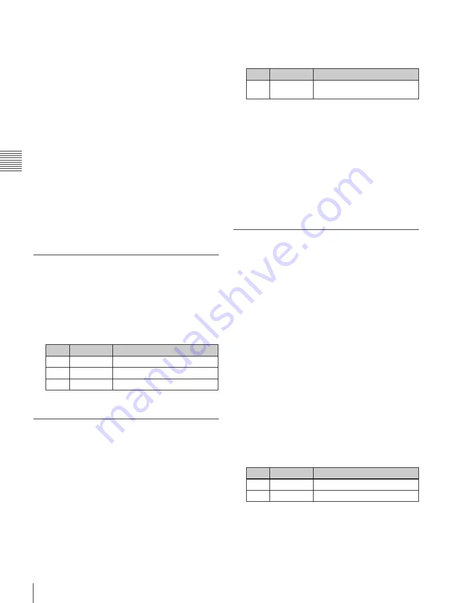
Adjust the following parameters.
No.
Parameter
Adjustment
2
White Clip
Luminance signal white clip value
3
Dark Clip
Luminance signal dark clip value
4
Chroma Clip Chrominance signal clip value
To set the values to the default values, press [Default].
Making Vertical Blanking Interval
Adjustment and Through Mode
Settings
This sets the number of scan lines from the reference
blanking position of field 1 for each format that should be
masked.
1
Open the Engineering Setup >Switcher >Output >V
Blank/Through menu (7333.3).
2
Select the output you want to set.
3
Press [V Blank Mask].
4
Adjust the following parameter.
No.
Parameter
Adjustment
2
Mask End
Final value for vertical blanking
interval
a)
a)
Depending on the signal format, the adjustment range varies as
follows.
480i: 10 to 19
576i: 6 to 22
1080i/1080PsF: 7 to 20
720P: 7 to 25
5
To enable through mode, press [Through Mode],
setting it to Enable. The following outputs can be
enabled.
•
Aux 1 to 24 outputs
•
Program outputs of the M/E and PGM/PST rows
•
Clean outputs of the M/E and PGM/PST rows
Making Safe Title Settings
1
Open the Engineering Setup >Switcher >Output >Safe
Title menu (7333.4).
The status area shows the output connectors and the
assigned signals, with the box 1, box 2, cross, and grid
states.
2
Select the output you want to set.
3
To enable the safe title on/off setting made in the Misc
menu, press [Safe Title], turning it on.
4
Carry out one of the following operations.
To display a box:
Press [Box1] or [Box2], turning it
on.
In this case, carry out the following steps
5
and
6
.
To display a cross:
Press [Cross], turning it on.
To display a grid:
Press [Grid], turning it on.
In this case, carry out the following steps
5
and
6
.
5
If you selected [Box1] or [Box2] in step
4
, adjust the
following parameters.
No.
Parameter
Adjustment
2
Box Size
Box size
3
Luminance
Display brightness
a)
a)
Adjustable for Box2
If [Grid] is selected in step
4
, in the <Grid Size> group,
select one of the following.
80.00%:
Sets the grid size to 80% of the screen frame.
85.00%:
Sets the grid size to 85% of the screen frame.


