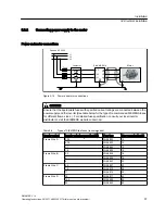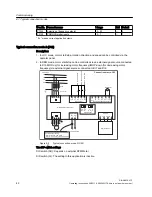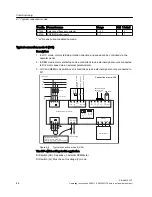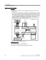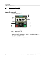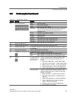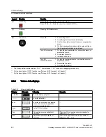
Typical connection mode 4 (C04)
Description:
1. In LOC mode, motor start/stop, rotation direction and speed can be controlled via the
operator panel.
2. In REM mode, motor start/stop can be controlled via an external signal source connected
to DI1, motor speed via an external potentiometer and motor rotation direction via an
external signal source connected to DI2.
L1
L2
3 AC 400 V
L3
PE
Fuse
Contactor
Connection macro: C04
PE L1
L3
L2
M
3~
U
V
W
O
N
/O
F
F
C
o
mma
n
d
F
W
D
/R
EV
C
o
mma
n
d
D
C
b
ra
ki
n
g
(o
p
ti
o
n
a
l)
5
+24V
0V
6
7
DI1
DI2
8
DI3
9
Digital Input
1
DO1 DO1
2
Digital Output
SINAMICS V10 Inverter
13
+10V
0V
RPM Meter
Speed Reference
Potentiometer
Analog Input/Analog Output
14
15
AI1- AI1+
AO1+
16
AO1-
17
18
N
N
220 AC Supply
L
DIP-switches
AO
(mA)
AO
(V)
I
U
AI
(mA)
AI
(V)
I
U
P6V5 M
RS-485
Com A Com B
Operator Panel
Factory defaut setting:
Inverter running: Lamp ON
Inverter in any other status: Lamp OFF
Figure 6-4
Typical connection mode 4 (C04)
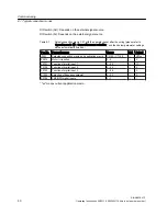
The DIP-switch settings
DIP-switch (AO): Depends on external RPM Meter
DIP-switch (AI): Must be set to voltage (V) mode
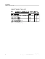
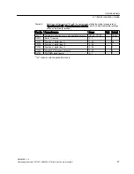
Table 6-4
Select connection macro C04 with the operator panel after the wiring (please refer to
"Operation mode
②
- Connection macro selection", and then below parameter settings
will be automatically finished.)
Par. No. Parameter name
Range
Unit
Default
r0007
Selected connection macro and application macro
C0100 - C1105
- -
C04xx*
P0610
Motor I
2
t reaction
0 - 2
- -
2
P0701
Function of digital input 1
0 - 99
- -
1
P0702
Function of digital input 2
0 - 99
- -
12
P0703
Function of digital input 3
0 - 99
- -
0
Commissioning
6.1 Typical connection modes
SINAMICS V10
Operating Instructions, 08/2011, A5E03453178 (this is not an order number)
45


