background image

5.2

Electrical installation

5.2.1

Interface definition


PE terminal layout 

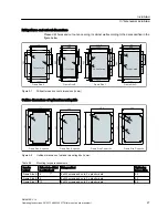
The position of PE terminals in Frame Size D is different from that in other frame sizes. See 

figure below for details. 

Frame Size A

Frame Size B

Frame Size C

Frame Size D

PE terminals 

PE terminals 

PE terminals

PE terminals

Figure 5-12 PE terminal layout

Table 5-5

Tightening torques for PE terminals

Inverter variant

Max. tightening torque for PE terminal (Nm)

Frame Size A

1.5

Frame Size B

1.5

Frame Size C

1.5

Frame Size D

2.5

Installation

5.2 Electrical installation

SINAMICS V10

Operating Instructions, 08/2011, A5E03453178 (this is not an order number)

33

Содержание SINAMICS V10

Страница 1: ...uctions SW version V 01 63 08 2011 A5E03453178 this is not an order number Introduction 1 Safety notes 2 Description 3 Identification 4 Installation 5 Commissioning 6 Parameter list 7 Troubleshooting 8 Technical data 9 Replacing the fans A ...

Страница 2: ... documentation in particular its warning notices and safety instructions Qualified personnel are those who based on their training and experience are capable of identifying risks and avoiding potential hazards when working with these products systems Proper use of Siemens products Note the following WARNING Siemens products may only be used for the applications described in the catalog and in the ...

Страница 3: ...erator panel 59 6 3 2 Various data displays 60 6 3 3 Displays during inverter initialization stage 62 6 4 Quick commissioning 63 6 5 Inverter status display 65 6 6 Overview of various operation modes 66 6 6 1 Operation mode Quick motor data setting 66 6 6 2 Operation mode Connection macro selection 67 6 6 3 Operation mode Application macro selection 69 6 6 4 Operation mode Common application macro...

Страница 4: ......

Страница 5: ...y updated information about the product at SIEMENS Website for the SINAMICS V10 Inverters http www ad siemens com cn products sd You can download the SINAMICS V10 user documentation at SIEMENS Website for the SINAMICS V10 User Documentation http www ad siemens com cn download Technical support In case of any questions concerning the product contact your local distributor SINAMICS V10 Operating Ins...

Страница 6: ......

Страница 7: ...ed with all the safety instructions installation connecting operation and maintenance procedures contained in this manual Any unauthorized modification of the equipment is NOT allowed To fulfill the requirements of CE and Low Voltage directives the equipment must be mounted in a metal cabinet and accessories like chokes should be used The equipment will automatically restart after a mains blackout...

Страница 8: ...condition NOTICE Keep this manual as a handy reminder and make them available to all users if necessary Identification WARNING Make sure that deliverables received are free from damage and in conformity with your purchase order Should any damage or inconsistence with the purchase order be found contact your local distributor or local dealer It s not permissible to put the equipment into use if it ...

Страница 9: ...automatic shutdown in case of a ground connection fault To avoid input power cable wires loosening or dropping from the mains input terminal connector use a proper clamp to secure the input power connections If you have to install a Residual Current operated protective Device RCD it must be an RCD type B Use of the protection from direct contact by means of SELV PELV is permitted only in areas wit...

Страница 10: ...owed to attempt to control the inverter operation via an external digital input CAUTION Motor commissioning under loaded conditions may only be performed after motor commissioning under no load dry run conditions Do not touch the inverter heatsink motor or other high temperature parts during equipment operation or within a certain period since power disconnection Failure to comply may cause person...

Страница 11: ... the machine to restart automatically Disposal WARNING Disposal of the equipment must be made in accordance with regulations of the competent environmental protection administration on the disposal of electronic wastes Safety notes SINAMICS V10 Operating Instructions 08 2011 A5E03453178 this is not an order number 11 ...

Страница 12: ......

Страница 13: ...table pulse frequency permits quiet motor operation Comprehensive protective functions provide excellent inverter and motor protection SINAMICS V10 with its default factory settings is ideal for a large range of simple motor control applications By configuring relevant parameters you can use the inverter for some advanced motor control operations In addition the SINAMICS V10 inverters are also sui...

Страница 14: ...n DC braking mode Compound braking to improve braking performance V f control with linear characteristic V f control with Flux Current Control FCC V f control with parabolic characteristic Acceleration deceleration times with programmable smoothing Integrated PI controller for simple process control Protection characteristics Short circuit protection Over current protection Inverter and motor over...

Страница 15: ... 0CE21 1UA1 1 5 kW 6SL3217 0CE21 5UA1 Frame Size B 2 2 kW 6SL3217 0CE22 2UA1 3 0 kW 6SL3217 0CE23 0UA1 4 0 kW 6SL3217 0CE24 0UA1 Frame Size C 5 5 kW 6SL3217 0CE25 5UA1 7 5 kW 6SL3217 0CE27 5UA1 11 kW 6SL3217 0CE31 1UA1 Frame Size D 15 kW 6SL3217 0CE31 5UA1 18 5 kW 6SL3217 0CE31 8UA1 22 kW 6SL3217 0CE32 2UA1 UDPH 6L H UDPH 6L H UDPH 6L H UDPH 6L H Quick Start Guide 1 English version 1 The documenta...

Страница 16: ...2XWSXW 9 0DGH LQ KLQD 3URWHFWLRQ 3 VHH PDQXDO Figure 4 1 Inverter rating plate example Inverter MLFB order number explanation SINAMICS V10 AC inverter frame size Rated mains input voltage 3 AC 380 V Unfiltered Rated output power Standard Hardware version Multiplier for output power 1 x 0 1 2 x 1 3 x 10 6 S L 3 2 1 7 0 C E 2 1 5 U A 1 Inverter variant kW Frame size A Frame size B Frame size C Frame...

Страница 17: ...2 Production Information Sheet 1 piece Plastic rivets 2 pieces Metal back cover 1 piece 3 Mounting screws Frame Size A 4 x M5 screws Frame Size B 4 x M5 screws Frame Size C 8 x M5 screws Frame Size D 8 x M5 screws 4 x M8 screws Mounting nuts Frame Size A 4 x M5 nuts Frame Size B 4 x M5 nuts Frame Size C 8 x M5 nuts Frame Size D 8 x M5 nuts 4 x M8 nuts Frame Size A specific 6SL3261 6AA00 0VA0 Frame...

Страница 18: ... refer to Technical data Page 115 Frame size Rated out put power Line commutating choke Output choke Frame Size A 0 55 kW 6SE6400 3CC00 2AD3 6SE6400 3CR00 2AD3 6SE6400 3TC0 0 4AD2 0 75 kW 6SE6400 3CC00 4AD3 6SE6400 3CR00 4AD3 1 1 kW 1 5 kW 6SE6400 3CC00 6AD3 6SE6400 3CR00 6AD3 Frame Size B 2 2 kW 6SE6400 3CC01 0BD3 6SE6400 3CR01 0BD3 6SE6400 3TC0 1 0BD3 3 0 kW 4 0 kW 6SE6400 3CC01 4BD3 6SE6400 3CR...

Страница 19: ...nformation Sheet 1 piece M3 Mounting screws 2 pieces The fan components for Frame Size C or Frame Size D include Fan 1 piece Production Information Sheet 1 piece M4 Mounting screws 2 pieces Spacers 2 pieces Frame Size B specific 6SL3200 0VF02 0AA0 Frame Size C specific 6SL3200 0VF03 0AA0 Frame Size D specific 6SL3200 0VF04 0AA0 Operator panel 6SL3200 0VB01 0AA0 Identification SINAMICS V10 Operatin...

Страница 20: ......

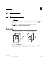
Страница 21: ...g outside the cabinet Do NOT mount the inverter horizontally in the cabinet Mounting orientation RUL RQWDO PRXQWLQJ RUELGGHQ 9HUWLFDO PRXQWLQJ LQ FDELQHW 0XVW QYHUWHU Figure 5 1 Mounting orientation When performing vertical mounting you can mount the inverter with an angle of 87 to 90 between inverter and horizontal surface See figure below for details SINAMICS V10 Operating Instructions 08 2011 A...

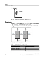
Страница 22: ...nd Table 5 1 below between the inverters 100 mm 100 mm 100 mm 100 mm A A A SINAMICS V10 SINAMICS V10 SINAMICS V10 SINAMICS V10 Figure 5 3 Inverter mounting clearance Table 5 1 Requirements for inverter mounting clearance Inverters positioned side by side Minimum clearance A in mm Frame Size A Frame Size A 50 Frame Size B Frame Size A B 50 Frame Size C Frame Size A B C 70 Frame Size D Frame Size A ...

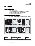
Страница 23: ...dimensions are also provided in the figure for your reference 5 8 155 138 114 211 5 140 230 5 8 142 159 150 124 260 242 7 192 5 218 203 11 186 331 311 230 260 223 210 401 373 8 8 UDPH 6L H UDPH 6L H UDPH 6L H UDPH 6L H ULOO SDWWHUQ ULOO SDWWHUQ ULOO SDWWHUQ ULOO SDWWHUQ Figure 5 4 Mounting dimensions in mm Table 5 2 Mounting torque requirements Inverter variant Holes to be drilled in cabinet wall ...

Страница 24: ...omplete your mounting of the inverter directly to cabinet wall Cabinet wall Mounting holes 1 Drill 4 holes in cabinet wall 1 Mounting holes Mounting screws Screw nuts 2 Mount the inverter to the wall and fix it with supplied mounting screws and screw nuts 2 Figure 5 5 Mounting sequence wall mounting Installation 5 1 Mechanical installation SINAMICS V10 24 Operating Instructions 08 2011 A5E03453178...

Страница 25: ...sh through mounting What does Push through mounting mean The term Push through mounting means 1 The inverter is mounted through cabinet wall using an optional push through mounting kit 2 The inverter body unit mounts inside cabinet while the heatsink extends outside the cabinet 3 If necessary you can use an external fan to cool the inverter Installation 5 1 Mechanical installation SINAMICS V10 Ope...

Страница 26: ...50 260 218 203 11 186 331 260 223 210 401 UDPH 6L H UDPH 6L H UDPH 6L H UDPH 6L H Figure 5 6 Outline dimensions of SINAMICS V10 in mm Installation 5 1 Mechanical installation SINAMICS V10 26 Operating Instructions 08 2011 A5E03453178 this is not an order number ...

Страница 27: ...nsions in mm Outline dimensions of optional mounting kits UDPH 6L H VSHFLILF UDPH 6L H VSHFLILF UDPH 6L H VSHFLILF UDPH 6L H VSHFLILF 257 6 361 8 5 8 2 4 1 4 10 294 445 172 262 4 5 8 182 292 4 5 8 4 5 8 Figure 5 8 Outline dimensions of optional mounting kits in mm Table 5 3 Mounting torque requirements Inverter variant Holes to be drilled in cabinet wall Fixing method Tightening torque Nm Frame Si...

Страница 28: ... the inverter to the push through mounting kit 2 x plastic rivets 2 5 8 x M5 screws and nuts for fixing the inverter to cabinet wall 2 5 4 x M4 screws for fixing the metal back cover to the back of inverter 0 8 Installation 5 1 Mechanical installation SINAMICS V10 28 Operating Instructions 08 2011 A5E03453178 this is not an order number ...

Страница 29: ...lowing procedure to complete your mounting of the inverter with optional mounting kit through cabinet wall Installation 5 1 Mechanical installation SINAMICS V10 Operating Instructions 08 2011 A5E03453178 this is not an order number 29 ...

Страница 30: ...ng Plastic rivet Mount the inverter to the mounting kit and tighten the 4 x M8 mounting screws and screw nuts 4 x M8 mounting screws Tightening torque 2 5 Nm 4 x M8 screw nuts Mounting the inverter to the cabinet wall then tighten the mounting screws and screw nuts delivered with the product Screw nuts Mounting screws This step is necessary only when mounting Frame Size D 0 6FUHZ 0HWDO EDFN FRYHU ...

Страница 31: ... remote operator panel operation 66 9 36 6 35 17 91 30 97 81 7 3 7 4 3 5 XW RXW DUHD DLQHW GRRU Figure 5 10 Mounting dimensions outline dimensions drill patterns cut out dimensions Table 5 4 Torques for fixing the operator panel to cabinet door Holes to be drilled in cabinet door Fixing method Tightening torque Nm 4 4 x M3 preassembled screw and washer assemblies screw length 12 mm 0 8 NOTICE If t...

Страница 32: ...UDWRU SDQHO IURP WKH LQYHUWHU ERG XQLW 5HPRYH WKH RSHUDWRU SDQHO IURP WKH LQYHUWHU ERG XQLW 0RXQW WKH RSHUDWRU SDQHO WR FDELQHW GRRU QWHUIDFH IRU FRQQHFWLQJ WKH RSHUDWRU SDQHO ZLWK LQYHUWHU ERG XQLW Figure 5 11 Procedure for mounting the operator panel to cabinet door Note For the cable connection between the operator panel and the inverter body unit see topic Interface definition Page 33 Installa...

Страница 33: ...ize B Frame Size C Frame Size D PE terminals PE terminals PE terminals PE terminals Figure 5 12 PE terminal layout Table 5 5 Tightening torques for PE terminals Inverter variant Max tightening torque for PE terminal Nm Frame Size A 1 5 Frame Size B 1 5 Frame Size C 1 5 Frame Size D 2 5 Installation 5 2 Electrical installation SINAMICS V10 Operating Instructions 08 2011 A5E03453178 this is not an o...

Страница 34: ...TCH Figure 5 13 Layout of interfaces other than PE terminals example Table 5 6 Tightening torques for motor output U V W and mains input terminals L1 L2 L3 Inverter variant Max tightening torque for motor output and mains input terminals Nm Frame Size A 0 6 Frame Size B 0 6 Frame Size C 1 2 Frame Size D 2 5 NOTICE Depending on your particular application you can set both DIP switches to required p...

Страница 35: ... cross section mains input cable Conductor cross section motor output cable mm2 AWG mm2 AWG Min Max Min Max Min Max Min Max A 0 55 1 0 1 5 17 0 15 0 1 0 1 5 17 0 15 0 0 75 1 0 1 5 17 0 15 0 1 0 1 5 17 0 15 0 1 1 1 0 1 5 17 0 15 0 1 0 1 5 17 0 15 0 1 5 1 0 1 5 17 0 15 0 1 0 1 5 17 0 15 0 B 2 2 1 0 2 5 17 0 13 0 1 0 4 0 17 0 11 0 3 1 0 2 5 17 0 13 0 1 0 4 0 17 0 11 0 4 1 5 2 5 15 0 13 0 1 0 4 0 17 0...

Страница 36: ...s of the DI DO AI AO terminal connecting cable Table 5 8 Conductor cross sections of the DI DO AI AO terminal connecting cable DO Digital Outputs DI Digital inputs AI Analog inputs AO Analog outputs Limit value mm2 1 2 0 1 0 1 0 1 Recommended value mm2 1 0 0 25 0 25 0 25 NOTICE To ensure that input output precision is 1 it s recommended that the cable length be less than 5 m If you don t have this...

Страница 37: ...For detailed fuse specification consult your local inverter distributor or visit the SIEMENS website concerned Table 5 9 Types of SIEMENS line fuses recommended Inverter variant Inverter output power rating kW Fuse type Fuse current rating A Frame Size A 0 55 3NA3803 10 0 75 3NA3803 10 1 1 3NA3803 10 1 5 3NA3803 10 Frame Size B 2 2 3NA3805 16 3 3NA3805 16 4 3NA3807 20 Frame Size C 5 5 3NA3807 20 7...

Страница 38: ......

Страница 39: ...e current exceeding 3 5 mA may occur during normal operation of the inverter A permanently fixed ground connection must be provided CAUTION The inverter digital input terminals analog input output terminals and the communication port between the inverter body unit and the operator panel should be double insulated from live parts and meet the requirements for SELV Safety Extra Low Voltage in EN6180...

Страница 40: ...only or unlocked parameters as per your particular demands Some default parameter values depend on specific connection macro inverter type motor rating data etc You can find detailed description of these parameters in Chapter 7 Parameter List Function of DC Braking can be enabled through proper settings of P0703 and P1230 In LOC mode default frequency setpoint depends on P1040 For relative paramet...

Страница 41: ...Inverter in any other status Lamp OFF L 13 10V 0V RPM Meter Operation from the inverter operator panel only Analog Input Analog Output 14 15 AI1 AI1 AO1 16 AO1 17 18 N DIP switches AO mA AO V I U AI mA AI V I U P6V5 M RS 485 Com A Com B Operator Panel Figure 6 1 Typical connection mode 1 C01 The DIP switch settings DIP switch AO Depends on external RPM Meter DIP switch AI The setting in this appli...

Страница 42: ...PE L1 L3 L2 M 3 U V W MOP up Command MOP down Command ON OFF Command 5 24V 0V 6 7 DI1 DI2 8 DI3 9 Digital Input 1 DO1 DO1 2 Digital Output SINAMICS V10 Inverter 13 10V 0V Analog Input Analog Output 14 15 AI1 AI1 AO1 16 AO1 17 18 RPM Meter N N 220 AC Supply L DIP switches AO mA AO V I U AI mA AI V I U P6V5 M RS 485 Com A Com B Operator Panel Lit while inverter running or alarm Dim while inverter fa...

Страница 43: ... operator panel 2 In REM mode motor start stop can be controlled via an external signal source connected to DI1 motor speed via an external potentiometer L1 L2 3 AC 400 V L3 PE Fuse Contactor Connection macro C03 PE L1 L3 L2 M 3 U V W ON OFF Command DC braking optional 5 24V 0V 6 7 DI1 DI2 8 DI3 9 Digital Input 1 DO1 DO1 2 Digital Output SINAMICS V10 Inverter 13 10V 0V RPM Meter Speed Reference Po...

Страница 44: ...ameter name Range Unit Default r0007 Selected connection macro and application macro C0100 C1105 C03xx P0610 Motor I2 t reaction 0 2 2 P0701 Function of digital input 1 0 99 1 P0702 Function of digital input 2 0 99 0 P0703 Function of digital input 3 0 99 0 P1000 Selection of frequency setpoint 0 53 2 P0725 PNP NPN digital inputs 0 1 1 xx means current application macro Commissioning 6 1 Typical c...

Страница 45: ...itches AO mA AO V I U AI mA AI V I U P6V5 M RS 485 Com A Com B Operator Panel Factory defaut setting Inverter running Lamp ON Inverter in any other status Lamp OFF Figure 6 4 Typical connection mode 4 C04 The DIP switch settings DIP switch AO Depends on external RPM Meter DIP switch AI Must be set to voltage V mode Table 6 4 Select connection macro C04 with the operator panel after the wiring plea...

Страница 46: ...ntiometer N ON OFF Command DC braking optional Manual Local Remote mode selection PE L1 L3 L2 M 3 U V W 5 24V 0V 6 7 DI1 DI2 8 DI3 9 Digital Input 1 DO1 DO1 0 10 V DC 2 Digital Output SINAMICS V10 Inverter 13 10V 0V Analog Input Analog Output 14 15 AI1 AI1 AO1 16 AO1 17 18 N 220 AC Supply L DIP switches AO mA AO V I U AI mA AI V I U P6V5 M RS 485 Com A Com B Operator Panel Lit while inverter runni...

Страница 47: ... connection macro and application macro C0100 C1105 C05xx P0610 Motor I2 t reaction 0 2 1 P0701 Function of digital input 1 0 99 99 P0702 Function of digital input 2 0 99 1 P0703 Function of digital input 3 0 99 0 P1000 Selection of frequency setpoint 0 53 2 P0725 PNP NPN digital inputs 0 1 1 xx means current application macro Commissioning 6 1 Typical connection modes SINAMICS V10 Operating Instr...

Страница 48: ... AC 400 V L3 PE Fuse Contactor Connection macro C06 ON OFF Command Set Frequency 1 Set Frequency 1 RPM Meter N PE L1 L3 L2 M 3 U V W 5 24V 0V 6 7 DI1 DI2 8 DI3 9 Digital Input 1 DO1 DO1 2 Digital Output SINAMICS V10 Inverter 13 10V 0V Analog Input Analog Output 14 15 AI1 AI1 AO1 16 AO1 17 18 N 220 AC Supply L DIP switches AO mA AO V I U AI mA AI V I U P6V5 M RS 485 Com A Com B Operator Panel Dim w...

Страница 49: ...motor start stop and rotation direction can be controlled via an external PLC PNP type connected to DI1 and DI2 motor speed via an external signal source L1 L2 3 AC 400 V L3 PE Fuse Contactor Connection macro C07 RPM Meter D A U AO M PLC PNP type outputs N PE L1 L3 ON FWD Command ON REV Command DC braking optional Speed Command L2 M 3 U V W 5 24V 0V 6 7 DI1 DI2 8 DI3 9 Digital Input 1 DO1 DO1 2 Di...

Страница 50: ... No Parameter name Range Unit Default r0007 Selected connection macro and application macro C0100 C1105 C07xx P0610 Motor I2 t reaction 0 2 2 P0701 Function of digital input 1 0 99 13 P0702 Function of digital input 2 0 99 2 P0703 Function of digital input 3 0 99 0 P1000 Selection of frequency setpoint 0 53 2 P0725 PNP NPN digital inputs 0 1 1 xx means current application macro Commissioning 6 1 T...

Страница 51: ...er running or alarm Dim while inverter fault Factory defaut setting Inverter running Lamp ON Inverter in any other status Lamp OFF Figure 6 8 Typical connection mode 8 C08 The DIP switch settings DIP switch AO Depends on the external signal source DIP switch AI Depends on the external signal source Table 6 8 Select connection macro C08 with the operator panel after the wiring please refer to Opera...

Страница 52: ...m A Com B Operator Panel DIP switches AO mA AO V I U AI mA AI V I U Lit while inverter running or alarm Dim while inverter fault Factory defaut setting Inverter running Lamp ON Inverter in any other status Lamp OFF Analog Input Analog Output Figure 6 9 Typical connection mode 9 C09 The DIP switch settings DIP switch AO Depends on external RPM Meter DIP switch AI Must be set to voltage V mode Table...

Страница 53: ...FF Command RPM Meter 0 10 V DC or 0 20 mA DC from Feedback Sensor N PE L1 L3 L2 M 3 U V W 5 24V 0V 6 7 DI1 DI2 8 DI3 9 Digital Input 1 DO1 DO1 2 Digital Output SINAMICS V10 Inverter 13 10V 0V Analog Input Analog Output 14 15 AI1 AI1 AO1 16 AO1 17 18 N 220 AC Supply L DIP switches AO mA AO V I U AI mA AI V I U P6V5 M RS 485 Com A Com B Operator Panel MOP up Command MOP down Command Lit while invert...

Страница 54: ...0 Selection of frequency setpoint 0 53 1 P0725 PNP NPN digital inputs 0 1 1 xx means current application macro NOTICE The PI controller function is valid only in this connection mode and when the current control mode is set to REM mode In this connection mode PI setpoint must be set via P2240 and feedback value shall depending on actually connected sensor be scaled via P0753 to P0761 Besides param...

Страница 55: ...ON Inverter in any other status Lamp OFF Speed Command Figure 6 11 Typical connection mode 11 C11 The DIP switch settings DIP switch AO Depends on external RPM Meter DIP switch AI The setting in this application is inactive Table 6 11 Select connection macro C10 with the operator panel after the wiring please refer to Operation mode Connection macro selection and then below parameter settings will...

Страница 56: ...y dead load Starting torque of common constant torque machine is relatively high which requires slow starting stopping Extruder injection molding machine stirring mill 1 A00 Out of box is the default application macro i e the application macro will be reset to A00 when a new connection macro is selected Parameters related to application macros Par No Name Range Unit Default value A00 A01 A02 A04 A...

Страница 57: ...ntroller 0 1 1 1 1 1 1 1 P1243 Dynamic factor of Vdc max 10 200 100 100 100 100 100 100 P1230 Enable DC braking 0 0 4 000 0 0 0 0 0 0 0 0 0 0 0 0 0 P1232 DC braking current 0 250 0 0 0 0 0 0 P1233 Duration of DC braking 0 250 s 0 0 0 0 0 0 P1200 Flying start 0 6 0 1 0 0 0 0 P1202 Motor current Flying start 10 200 100 100 100 100 100 100 P1203 Search rate Flying start 10 200 100 100 100 100 100 100...

Страница 58: ...P SET RUN Figure 6 12 Operator panel overview Monitor motor status Control motor operation Start stop speed clockwise counterclockwise rotation etc View and acknowledge faults or alarms Set and modify parameters Switch over between LOC and REM controls Commissioning 6 3 Operator panel overview SINAMICS V10 58 Operating Instructions 08 2011 A5E03453178 this is not an order number ...

Страница 59: ...LOC REM Switch between local and remote control modes 1 LOC Motor operation is controlled from the operator panel REM Motor operation is controlled from an external signal source SET key 䆒㕂 SET Long press SET till the next operation mode appears Change over between the following operation modes See section Quick commissioning Page 63 for details 1 Quick motor data setting Inverter status display 2...

Страница 60: ...int 1 The factory default control mode is LOC In most cases LOC is used for debugging purpose only 2 For the description of OFF1 function see Notes on OFF functions in Chapter 7 3 For the description of OFF2 function see Notes on OFF functions in Chapter 7 6 3 2 Various data displays Table 6 14 Various data displays Display Example Meaning Remarks 8 8 8 8 8 Inverter display is lighted Inverter ini...

Страница 61: ...alarm in case of multiple alarms The inverter can display up to 4 recently occurred alarms in turn Alarm code of the 2nd alarm in case of multiple alarms Err Value setting impossible Error parameter editing It s a warning indicating that what you re trying to edit is a read only parameter and such editing is not allowed xxx xx Parameter value positive Display a positive value of 5 digits at most x...

Страница 62: ...ULT ALARM LOCAL REMOTE REVERSE RUN STOP WAIT Rpm A SETTING TUNE V Hz kW 䖤㸠 ذ 䔺 ᕙᴎ 䆒㕂 䇗䇤 ᬙ䱰 䄺 ᴀഄ 䖰 ড䕀 FAULT ALARM LOCAL REMOTE REVERSE RUN STOP WAIT Rpm A SETTING TUNE V Hz kW 䖤㸠 ذ 䔺 ᕙᴎ 䆒㕂 䇗䇤 ᬙ䱰 䄺 ᴀഄ 䖰 ড䕀 FAULT ALARM LOCAL REMOTE REVERSE RUN STOP WAIT SETTING TUNE 䖤㸠 ذ 䔺 ᕙᴎ 䆒㕂 䇗䇤 ᬙ䱰 䄺 ᴀഄ 䖰 ড䕀 Figure 6 14 Displays during inverter initialization stage Commissioning 6 3 Operator panel overview SINAMIC...

Страница 63: ...UNE V Hz kW 䖤㸠 ذ 䔺 ᕙᴎ 䆒㕂 䇗䇤 ᬙ䱰 䄺 ᴀഄ 䖰 ড䕀 2SHUDWLRQ PRGHཱ RQQHFWLRQ PDFUR VHOHFWLRQ FAULT ALARM LOCAL REMOTE REVERSE RUN STOP WAIT Rpm A SETTING TUNE V Hz kW 䖤㸠 ذ 䔺 ᕙᴎ 䆒㕂 䇗䇤 ᬙ䱰 䄺 ᴀഄ 䖰 ড䕀 2SHUDWLRQ PRGHི SSOLFDWLRQ PRGH VHOHFWLRQ RQJ SUHVV RQJ SUHVV RQJ SUHVV RQJ SUHVV 䆒㕂 SET 䆒㕂 SET 䆒㕂 SET 䆒㕂 SET 䆒㕂 SET 6KRUW SUHVV 6KRUW SUHVV 6KRUW SUHVV 3UHVV 6KRUW SUHVV 䆒㕂 SET 䆒㕂 SET 䆒㕂 SET 䆒㕂 SET 0RWRU SDUDPHWHU...

Страница 64: ... Motor Type Rated speed rpm Rated motor efficiency Power factor Rated current A Rated torque Nm 0 55 80M 1LG0080 4AA 1390 71 0 0 750 1 57 3 8 0 75 80M 1LG0083 4AA 1380 73 0 0 760 2 05 5 2 1 1 90S 1LG0090 4AA 1390 76 2 0 760 2 89 7 6 1 50 90L 1LG0096 4AA 1390 78 5 0 790 3 67 10 3 2 20 100L 1LG0106 4AA 1410 81 0 0 800 5 16 14 9 3 00 100L 1LG0107 4AA 1410 82 8 0 810 6 80 20 3 4 00 112M 1LG0113 4AA 14...

Страница 65: ...en stop turning OK the value shown is an actual value and the inverter status indicator for SETTING becomes invisible Automatically after 3 seconds Initial setpoint Decreased setpoint Increased setpoint Actual frequency value Turn SETTING SETTING SETTING SETTING OK Turn OK Turn OK Figure 6 17 Frequency status changeover example Note The default display at first power on is the frequency To change ...

Страница 66: ...CE P 0304 is always the default display in this mode Parameters available for setting in this mode can also be shown in the Access all the parameters mode However in the Access all the parameters mode these parameters are read only To easily differentiate the parameter number shown in the Quick motor data setting mode has a dot after P Commissioning 6 6 Overview of various operation modes SINAMICS...

Страница 67: ... LV VWLOO QRW ZKDW RX ZDQW UHSHDW WKH DIRUH VDLG RU OWHUQDWLYH WLOO WKH ULJKW YDOXH DSSHDUV SET Figure 6 19 Parameter setting example P0304 Note The value set by pressing OK will be displayed by default next time The digit bit can be dynamically changed according to the parameter value Button keys inactive in this mode The STOP RUN and LOC REM keys are inactive in this mode 6 6 2 Operation mode Co...

Страница 68: ...Automatically Inverter is confirming the selection Press OK OK Turn Figure 6 21 Connection macro setting example NOTICE If the inverter is confirming the selection of a connection macro time consumption is about 50 seconds if it is confirming the selection of an application macro the time consumption is about 20 seconds Button keys inactive in this mode The STOP RUN and LOC REM keys are inactive i...

Страница 69: ... Press OK OK Turn Figure 6 23 Application macro setting example NOTICE If the inverter is confirming the selection of a connection macro time consumption is about 50 seconds if it is confirming the selection of an application macro the time consumption is about 20 seconds Button keys inactive in this mode The STOP RUN and LOC REM keys are inactive in this mode See also Application macros Page 56 C...

Страница 70: ...mber shown in the Common application macro specific parameter setting mode has a dot after P You can set a parameter value either in this mode or in the Access all parameters mode Once the value is set it will be simultaneously updated in both modes Parameter setting in Application macro specific parameter setting mode See the second figure in topic Operation mode Quick motor data setting Page 66 ...

Страница 71: ...parameters mode Setting a normal parameter See the second figure in topic Operation mode Quick motor data setting Page 66 for parameterization method Setting an indexed parameter Example r0207 2 OK OK Turn OK Turn Press OK Press OK Press 7KLV GLVSOD LQGLFDWHV WKDW FKDQJLQJ D UHDG RQO YDOXH LV LPSRVVLEOH Figure 6 26 Setting an indexed parameter example Viewing a normal read only parameter Example r...

Страница 72: ...Then the display will automatically jump to the next immediately followed and available for setting value Button keys inactive in this mode If the current connection macro selected is C01xx or C05xx the LOC REM key is inactive in this mode The STOP and RUN keys are active when one of the preconfigured connection modes is selected and currently the command source is from the operator panel The OK b...

Страница 73: ...s been completed successfully the operator panel display returns to its normal state while the inverter returns to a ready state 8 If the parameter uploading has failed F0055 will be displayed on the operator panel In this case please check the operator panel to clear this fault and try uploading parameters again 9 Remove the operator panel from the inverter 10 Connect the operator panel to a new ...

Страница 74: ...ameter cloning Only the current datasheet is uploaded to the operator panel Once begun the cloning procedure can not be interrupted Parameters can be copied between inverters of different power ratings but motor specific parameters P0611 and P0640 can not be copied During the downloading work if the data are not compatible with the inverter the default values for the parameters will be written int...

Страница 75: ...rter current r0208 Rated inverter voltage r0209 Max inverter current r0752 Act input of ADC V r0947 8 Last fault code r1119 CO Freq setpoint before RFG r2036 Ctr Wrd1 from operator panel r2110 4 Warning number Table 7 2 Motor data for quick commissioning Parameter No Name P0304 Rated motor voltage P0305 Rated motor current P0307 Rated motor power P0308 Rated motor cosPhi P0309 Rated motor efficien...

Страница 76: ...Smooth time DAC P0777 Value x1 of DAC scaling P0778 Value y1 of DAC scaling P0779 Value x2 of DAC scaling P0780 Value y2 of DAC scaling P0781 Width of DAC deadband Table 7 5 Frequency reference specific parameters Parameter No Name P1040 Setpoint of the MOP P1000 Selection of freq setpoint P1074 Disabling an additional setpoint P1020 Fixed frequency selection 1 P1021 Fixed frequency selection 2 P1...

Страница 77: ...ter ramp down P1230 BI Enable DC braking P1232 DC braking current P1233 Duration of DC braking P1236 Compound braking current P1310 Continuous boost P1311 Acceleration boost P1312 Starting boost P1910 Select motor data identification P2200 Enable PI controller P2231 Setpoint memory of PI MOP P2240 Setpoint of PI r2262 Filtered PI setpoint after RFG r2272 PI scaled feedback r2273 PI error P2291 PI ...

Страница 78: ...ntroller P1300 Control mode P1800 Pulse frequency P2000 Reference frequency P2280 PI proprotion gain P2285 PI integral time P2293 Ramp up down time of PI limit Notes on the OFF functions OFF1 This command produced by cancelling the ON command causes the inverter to come to a standstill at the selected ramp down rate Active by pressing STOP for less than 2 seconds OFF2 This command causes the motor...

Страница 79: ... and application macro C0100 C1005 C0100 Displays selected connection macro and application macro C0100 Connection macro C01 and application macro A00 are selected C0101 Connection macro C01 and application macro A01 are selected C1005 Connection macro C10 and application macro A05 are selected Note Default value depends on selected connection macro and application macro P0011 Lock for user define...

Страница 80: ...rform a factory reset of all parameters except parameters for quick motor data settings and selected connection macro The default values of P0011 lock and P0012 key are the same r0018 2 Inverter version display Displays firmware version number of the inverter or the operator panel r0018 0 Inverter firmware version r0018 1 Firmware version of the operator panel r0024 Actual Inverter output frequenc...

Страница 81: ...ion of the 7 segment display of the bit parameters binary parameters see topic Operator panel overview Page 58 r0206 Rated inverter power kW Displays nominal rated motor power from inverter r0207 2 Rated inverter current A Displays maximum continuous output current of inverter r0207 0 Rated inverter current r0207 1 Rated motor current of a 4 pole 1LA7 AC motor Note Under this index 1 you can only ...

Страница 82: ...0 0 100 0 95 0 Defines the value at which alarm A0505 inverter I2 t is generated Inverter I2 t calculation is used to determine a maximum tolerable period for inverter overload The I2 t calculation value is deemed 100 when this maximum tolerable period is reached Note P0294 100 corresponds to stationary nominal load P0304 Rated motor voltage 10 2000 400 V Nominal motor voltage V from rating plate ...

Страница 83: ...ol and V f control with speed controller P0320 Motor magnetizing current 0 0 99 0 0 0 Defines motor magnetization current in relative to P0305 rated motor current P0335 Motor cooling 0 1 0 Selects motor cooling system used Possible settings 0 Self cooled Using shaft mounted fan attached to motor 1 Forced cooled Using separately powered cooling fan P0350 Stator resistance line to line 0 0001 2000 0...

Страница 84: ...motor parameters during quick commissioning is complete the stored value can be replaced by the value given by the motor manufacturer P0640 Motor overload factor 10 0 400 0 110 0 Defines motor overload current limit in relative to P0305 rated motor current P0701 Function of digital input 1 0 99 0 Selects function of digital input 1 Possible settings 0 Digital input disabled 1 ON OFF 1 2 ON reverse...

Страница 85: ...r0722 Binary input values Displays status of digital inputs Bitfields Bit00 Digital input 1 0 OFF 1 ON Bit01 Digital input 2 0 OFF 1 ON Bit02 Digital input 3 0 OFF 1 ON Note Segment is lit when signal is active The 7 segment display of the bit parameters binary parameters is explained in Fig 6 12 of Section 6 3 2 P0725 PNP NPN digital inputs 0 1 1 Switches between active high PNP and active low NP...

Страница 86: ...e meaning of individual value settings Note The meaning of 2036 0 corresponds to the description of Bit00 The meaning of 2036 1 corresponds to the description of Bit01 the rest on the analogy of it P0748 Invert digital outputs 0 1 0 Defines high and low states of relay for a given function Bitfields Bit00 Invert digital output 1 0 NO 1 YES Note The 7 segment display of the bit parameters binary pa...

Страница 87: ... V 0 mA 0 and 10 V 20 mA 100 Note The value x2 of ADC scaling P0759 must be greater than the value x1 of ADC scaling P0757 If P2200 1 P0757 to P0760 can only be set for PI feedback scaling P0758 Value y1 of ADC scaling 99999 99999 0 00 Sets value of Y1 in as described in P0757 ADC scaling P0759 Value x2 of ADC scaling V 0 00 10 00 10 00 V Sets value of x2 as described in P0757 ADC scaling Note The...

Страница 88: ...es x1 output characteristic in Scaling block is responsible for adjustment of output value defined in P0771 DAC connector input Parameters of DAC scaling block P0777 P0781 work as follows Output signal mA 20 0 P0777 100 x1 P0779 x2 P0780 y2 P0778 y1 Where Points P1 x1 y1 and P2 x2 y2 can be chosen freely P0778 Value y1 of DAC scaling 0 00 20 00 0 00 Defines y1 of output characteristic P0779 Value ...

Страница 89: ...er to the operator panel Possible settings 0 Disabled 1 Upload P0801 Parameter download from operator panel to inverter 0 1 0 With this parameter you can download parameters from the operator panel to an inverter Possible settings 0 Disabled 1 Download Parameter list SINAMICS V10 Operating Instructions 08 2011 A5E03453178 this is not an order number 89 ...

Страница 90: ...DXOWV LQ ಯ8SGDWHG IDXOW KLVWRU ಯ Where Acknowledging the active faults will moves the value in the 2 indicates down to the next pair of indicates where they are stored Indicates 0 1contain the active faults When faults are acknowledged indicates 0 1 are reset to 0 Index r0947 0 Recent fault trip fault 1 r0947 1 Recent fault trip fault 2 r0947 2 Recent fault trip 1 fault 3 r0947 3 Recent fault trip...

Страница 91: ...7 P0311 P0320 P0335 P0350 and connection macro settings reset P0971 Transfer data from RAM to EEPROM 0 1 0 Transfers values from RAM to EEPROM After parameterization by the user he can Possible settings 0 Disabled 1 Start transfer Note All values in RAM are transferred to EEPROM Parameter is automatically reset to 0 default after successful transfer Parameter list SINAMICS V10 Operating Instructio...

Страница 92: ...operation panel Analog setpoint can be used for C11 if the function of DI reconfigured 31 MOP setpoint Fixed frequency can be used for the remote mode of C02 C10 and C11 if the function of DI reconfigured 32 Analog setpoint Fixed frequency can be used for the remote mode of C02 C10 and C11 if the function of DI reconfigured 35 operation panel Fixed frequency can be used for C11 if the function of ...

Страница 93: ...selection of fixed frequencies 1 Direct selection P0701 P0703 15 In this mode of operation 1 digital input selects 1 fixed frequency If several inputs are active at the same time the selected frequencies are summed up 2 Direct selection ON command P0701 P0703 16 The fixed frequency selection integrates fixed frequencies with an ON command In this mode of operation 1 digital input selects 1 fixed f...

Страница 94: ...0 5 00 Hz Jogging increases the motor frequency by small amounts The JOG buttons uses a non latching switch on one of the digital inputs to control the motor frequency While JOG right is selected this parameter determines the frequency at which the inverter will run P1059 JOG frequency left 0 00 300 00 5 00 Hz While JOG left is selected this parameter determines the frequency at which the inverter...

Страница 95: ...s to the description of Bit00 The meaning of 52 1 corresponds to the description of Bit01 the rest on the analogy of it 722 0 722 2 See parameter r0722 for the meaning of individual value settings Note The meaning of 722 0 corresponds to the description of Bit00 The meaning of 722 1 corresponds to the description of Bit01 the rest on the analogy of it 2036 0 2036 F See parameter r0236 for the mean...

Страница 96: ... modification by other functions e g P1110 BI Inhibit neg frequency setpoint P1091 skip frequencies P1082 Min frequency P1082 Max frequency Limitations Etc P1120 Ramp up time 0 00 300 00 30 00 s Time taken for motor to accelerate from standstill up to maximum motor frequency P1082 when no rounding is used Note Setting the ramp up time too short can cause the inverter to trip overcurrent If an exam...

Страница 97: ...ettings 0 Flying start disabled 1 Flying start is always active start in direction of setpoint 2 Flying start is active if power on fault OFF2 start in direction of setpoint 3 Flying start is active if fault OFF2 start in direction of setpiont 4 Flying start is active only in direction of setpoint 5 Flying start if power on fault OFF2 only indirection of setpoint 6 Flying start if active if fault ...

Страница 98: ...kout Brownout Blackout Blackout 0 1 Fault ack Fault ack Fault ack 2 Fault ack restart Restart 3 Fault ack restart Fault ack restart Fault ack restart Fault ack restart Fault ack restart 4 Fault ack restart Fault ack restart 5 Fault ack restart Fault ack restart Fault ack restart Restart 6 Fault ack restart Fault ack restart Fault ack restart Fault ack restart Fault ack restart Restart Note Flying ...

Страница 99: ...e motor has been sufficiently demagnetized Possible settings 722 0 Digital input 1 requires P0701 to be set to 99 BICO 722 1 Digital input 2 requires P0702 to be set to 99 BICO 722 3 Digital input 3 requires P0703 to be set to 99 BICO Cautions With the DC braking the kinetic energy of the motor is converted into heat in the motor The drive could overheat if it remains at this status for an exessiv...

Страница 100: ...6 1 250 Level of DC braking current defined as a of rated motor current P0305 Dependency Compound braking depends on the DC link voltage only It will be active with OFF1 OFF3 and at regenerating conditions It is disabled when DC braking is active Flying start is active Notice Increasing the value will generally improve braking performance however if you set the value too high an overcurrent trip m...

Страница 101: ... or quadratic after an ON command and is active until 1 ramp output reaches setpoint for the first time respectively 2 setpoint is reduced to less than present ramp output This is useful for starting loads with high inertia Setting the starting boost P1312 too high will cause the inverter to limit the current which will in turn restrict the output frequency P1800 Pulse frequency 2 16 4 kHz Sets pu...

Страница 102: ... Fault acknowledge 0 NO 1 YES Bit08 JOG right 0 NO 1 YES Bit09 JOG left 0 NO 1 YES Bit10 Control from the operator panel 0 NO 1 YES Bit11 Reverse setpoint inversion 0 NO 1 YES Bit13 Motor potentiometer MOP up 0 NO 1 YES Bit14 Motor potentiometer MOP down 0 NO 1 YES Bit15 Local Remote 0 NO 1 YES Note The 7 segment display of the bit parameters binary parameters is explained in Fig 6 12 of Section 6...

Страница 103: ...ds to the description of Bit01 the rest on the analogy of it Note If P2200 1 PI feedback scaled value of ADC output For details see P0757 to P0760 P2231 Setpoint memory of PI MOP 0 1 0 Setpoint memory Possible settings 0 PI MOP setpoint will not be stored 1 PI MOP setpoint will be stored P2240 is updated Dependency If 0 is selected setpoint returns to the value set in P2240 setpoint of PI MOP afte...

Страница 104: ...reference frequency P2292 PI output lower limit 200 00 200 00 0 00 Sets lower limit fort he PI controller output in Dependency A negative value allows bipolar operation of PI controller Note P2292 100 corresponds to 4 000 hex P2293 Ramp up down time of PI limit 0 00 100 00 1 00 s Sets maximum ramp rate on output of PI When PI is enabled the output limits are ramped up from 0 to 100 Limits prevent ...

Страница 105: ...000 1 00 C03 C03xx 2 1 0 0 1 2 3 000 0 000 1 00 C04 C04xx 2 1 12 0 1 2 3 000 0 000 1 00 C05 C05xx 1 99 1 0 1 2 3 000 0 000 1 00 C06 C06xx 2 1 15 15 1 3 3 000 0 000 1 00 C07 C07xx 2 1 2 0 1 2 3 000 0 000 1 00 C08 C08xx 2 1 2 0 0 2 3 000 0 000 1 00 C09 C09xx 2 1 10 11 1 2 3 000 0 000 1 00 C10 C10xx 2 1 13 14 1 1 0 500 10 000 10 00 C11 C11xx 2 1 12 9 1 5 3 000 0 000 1 00 xx means current application ...

Страница 106: ......

Страница 107: ...e OK button 2 Set the current control mode to LOCAL status 3 Long press the SET key to go to Operation mode Access all the parameters Page 71 mode 4 Turn OK to find the fault specific parameter 5 Correct wrong parameter setting then wait till the fault code appears again 6 Short press the SET key to clear the fault code If necessary you can then set the control mode to REMOTE status Note 1 When C1...

Страница 108: ...knowledging and clearing F0003 example Alternative 2 Re power on the inverter Alternative 3 If a digital input terminal has been configured as the fault clearance terminal via either one of the parameters P0701 to P0703 acknowledge and clear the fault via the digital input terminal NOTICE When multi faults occur the fault code is always displayed as x Fxxx For example 1 F002 The first fault code F...

Страница 109: ... with a lower power rating Is the stator resistance value P0350 correct F0002 Overvoltage DC link voltage r0026 higher than the overvoltage threshold refer to parameter r0026 Ground fault Is the line supply voltage within the permissible range Has the DC current DC link monitoring been enabled P1240 and correctly parameterized Extend the deceleration ramp ramp down time P1121 P1135 Remove the grou...

Страница 110: ...lt Read error power data or invalid power module data Contact your local distributor F0055 Operator panel EEPROM fault Read or write failure while saving non volatile parameter to EEPROM on the operator panel whilst parameter cloning Re upload parameters Replace the operator panel F0056 Parameters downloading failed Fail to download parameters whilst parameter downloading Re download the parameter...

Страница 111: ...ck below 0 Adjust feedback gain Adjust ACD parameter setting F0222 PI Feedback above maximum value PI feedback above 200 Adjust feedback gain F0422 No load applied to inverter No load is applied to the inverter As a result some functions may not work as under normal load conditions Apply the load F0450 BIST tests unsuccessful Self test routine for power module components unsuccessful Several funct...

Страница 112: ...er r0026 Check supply voltage P0210 A0504 Inverter overtemperature Alarm threshold of the inverter heatsink temperature was exceeded This results in a reduction of the pulse frequency and or the output frequency dependent on the parameterization in P0610 Is the ambient temperature within the permissible limits Are the load and load duty cycle within the permissible limits A0505 Inverter I2 T Overl...

Страница 113: ...lly result in an under voltage trip Check parameter inverter input voltage Check ramp up times A0920 ADC parameters not set properly ADC parameters should not be set to identical values since this would produce illogical results Analogue input parameters should not be set to the same value as each other A0921 DAC parameters not set properly DAC parameters P0777 vs P0779 or P0778 vs P0780 have iden...

Страница 114: ......

Страница 115: ... 2 18 4 26 0 32 0 38 0 45 0 4 kHz 1 7 2 2 3 1 4 1 5 9 7 7 10 2 13 2 18 4 26 0 32 0 38 0 45 0 6 kHz 1 7 2 2 3 1 4 1 5 9 7 7 10 2 13 2 18 4 26 0 27 2 32 3 38 3 8 kHz 1 7 2 2 2 7 2 7 5 1 5 1 6 7 13 2 13 2 17 9 22 4 26 6 31 5 10 kHz 1 7 2 2 2 7 2 7 5 1 5 1 6 7 13 2 13 2 17 9 19 2 22 8 27 0 12 kHz 1 7 1 6 1 6 1 6 3 6 3 6 4 8 9 6 9 6 13 5 16 0 19 0 23 2 14 kHz 1 7 1 6 1 6 1 6 3 6 3 6 4 8 9 6 9 6 13 5 14...

Страница 116: ...tions Short circuit protection Over current protection Over Under voltage protection Inverter and motor over temperature protections Ground fault protection Stall prevention Motor blocking protection Parameter interlock Max Motor cable length Without choke Unshielded 50 m 50 m 100 m 100 m Shielded 30 m 30 m 50 m 50 m With choke Unshielded 100 m 100 m 200 m 250 m Shielded 60 m 60 m 100 m 150 m Mech...

Страница 117: ...excluding all input output terminals 8 Standards CE mark in accordance with Low Voltage Directive 2006 95 EC 1 Unless otherwise specified the output current indicated refers to the value that can be reached when the ambient temperature is at 50 C 2 Can be operated on TNC TNS TT or IT excluding three phase three wire systems unearthed or corner earthed Can also be operated on the three phase three ...

Страница 118: ...pecified in of the max mains input voltage 8 The protection class of all input output terminals is IP00 NOTICE If customers use external 24 V power supply the range of this power supply should be from DC19 6V to DC28 8V For detailed wirings please refer to connection modes in Typical connection modes Page 39 Technical data SINAMICS V10 118 Operating Instructions 08 2011 A5E03453178 this is not an ...

Страница 119: ...cover Fan cover Fan Connector on the fan Connectors on inverter housing Connector on the fan 4 M3 mounting screws Tightening torque 0 8 Nm Frame Size B Remove the fan covers from the fans 2 1 Remove the mounting screws from the fan covers Remove the fans from the inverter by manually detaching connectors on the fans from mating connectors on the housing 3 Figure A 1 Removing the fans from Frame Si...

Страница 120: ...ns inside from the inverter by manually detaching connectors on the fans from the mating connectors on the housing 2 1 3 4 Metal spacers Fan Fan Fan cover Connector on fans Connector on fans Remove the mounting screws from the fan cover Pull the fans out of the fan cover Pull the metal spaces out of the fans Figure A 2 Removing the fans from Frame Size C Replacing the fans SINAMICS V10 120 Operati...

Страница 121: ...h Frame Size D Remove the mounting screws from the fans Remove the fans from the inverter by pressing the hook on the fan connector to manually detach connectors on the fans from the mating connectors on the housing 4 Pull the 4 fan spacers out of the fans Apply a downward pressure to the latches and pull outward the fan cover from the inverter Figure A 3 Removing the fans from Frame Size D Replac...

Страница 122: ......

Страница 123: ...delivery 15 Spare parts 19 E Electrical installation Conductor cross sections of the DI DO AI AO terminal connecting cable 36 Conductor cross sections of the mains input cable and the motor output cable 35 Interfaces between inverter body unit and the remote operator panel 35 Layout of interfaces other than PE terminals 34 PE terminal layout 33 Power and motor connections 37 M Mechanical installat...

Страница 124: ......

Отзывы: