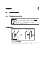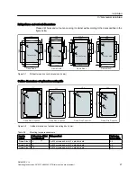
,QYHUWHUIURQW
PLQLQXP
+RUL]RQWDO
&DELQHWZDOO
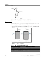
Figure 5-2
Allowed mounting angle between inverter and the horizon
Mounting clearance
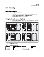
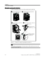
You can mount inverters one next to another or one above another with the clearance below:
● Allow at least 100 mm clearance above and below the inverter..
● Allow at least specified clearance A (see Figure 5-3 and Table 5-1 below) between the
inverters.
≥100 mm
≥100 mm
≥100 mm
≥100 mm
A
A
A
SINAMICS V10
SINAMICS V10
SINAMICS V10
SINAMICS V10
Figure 5-3
Inverter mounting clearance
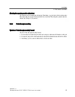
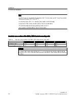
Table 5-1
Requirements for inverter mounting clearance
Inverters positioned side by side
Minimum clearance ("A") in mm
Frame Size A ↔ Frame Size A
50
Frame Size B ↔ Frame Size A / B
50
Frame Size C ↔ Frame Size A / B / C
70
Frame Size D ↔ Frame Size A / B / C / D
75
Installation
5.1 Mechanical installation
SINAMICS V10
22
Operating Instructions, 08/2011, A5E03453178 (this is not an order number)

