CAUTION
Do not install the equipment in an area where it is likely to be exposed to constant vibrations,
physical shocks or interference from electromagnetic field.
Risk of fire. Make sure that no foreign body (e.g., chips of wood or metal, dust, paper, etc.)
falls into the inverter or lie on the heatsink of the inverter.
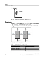
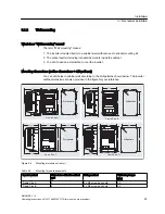
Keep sufficient clearance between inverters, one inverter and another device/the inner wall
of the cabinet. (See topic "Mounting orientation and clearance (Page 21)" for clearance
requirements).
The inverter MUST NOT be mounted horizontally.
Connecting
WARNING
The inverter must have been disconnected from the power supply for at least five minutes
before you perform any wiring to the inverter.
Make sure that all connections are correct and reliable. Only permanently-wired input power
connections are allowed and the inverter must be well grounded (IEC 536 Class 1, NEC and
other applicable standards).
According to IEC 61800-5-1, a PDS (Power Drive System) with leakage currents over 3.5
mA requires a secure ground connection (e.g., at least 10 mm
2
Cu or multiple connection) or
an automatic shutdown in case of a ground connection fault.
To avoid input power cable wires loosening or dropping from the mains input terminal
connector, use a proper clamp to secure the input power connections.
If you have to install a Residual Current-operated protective Device (RCD), it must be an
RCD type B.
Use of the protection from direct contact by means of SELV/PELV is permitted only in areas
with equipotential bonding and in dry interior spaces. If these conditions are not present, other
protective measures against electric shock must be taken, e.g., protection through protective
impedances or limited voltage or use of protection class I and II.
Only PELV or SELV voltages may be connected at terminals with either PELV or SELV
voltages (refer to EN 60204-1, Section 6.4).
CAUTION
The rated mains input voltage to the inverter must be 3 AC 400 V.
Never connect the mains input cable to the motor terminals U, V, W or connect the motor
cable to the mains input terminals L1, L2, L3.
Route signal cables and power cables separately in different cable conduits. The signal
cables shall be at least 10 cm away from the power cables.
Keep connecting cables away from rotating mechanical parts.
Safety notes
SINAMICS V10
Operating Instructions, 08/2011, A5E03453178 (this is not an order number)
9

