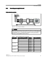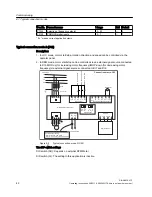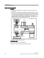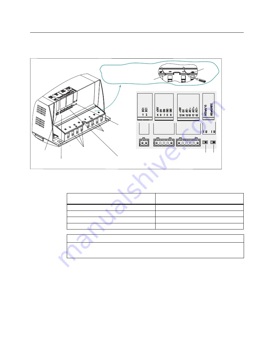
Layout of interfaces other than PE terminals
Frame Size D
Mains input connection
(L1, L2, L3)
Motor output connection
(U, V, W)
Digital outputs
(1, 2)
Digital inputs
(5, 6, 7, 8, 9)
Analog inputs/outputs
(13, 14, 15, 16, 17, 18)
DIP-switches
Factory default positions
For Frame Size D, it’s necessary to
lever up the housing cover before
wiring.
Cover lock
Cover lock
DIGITAL
OUTPUT
DIGITAL
INPUT
ANALOG INPUT
AND OUTPUT
IU
SWITCH
Figure 5-13 Layout of interfaces other than PE terminals (example)
Table 5-6
Tightening torques for motor output (U, V, W) and mains input terminals (L1, L2, L3)
Inverter variant
Max. tightening torque for motor output and mains
input terminals (Nm)
Frame Size A
0.6
Frame Size B
0.6
Frame Size C
1.2
Frame Size D
2.5
NOTICE
Depending on your particular application, you can set both DIP-switches to required positions.
Digital inputs and analog inputs/outputs provide the SELV voltages.
Installation
5.2 Electrical installation
SINAMICS V10
34
Operating Instructions, 08/2011, A5E03453178 (this is not an order number)


