Semiconductor Group
6-53
1999-04-01
On-Chip Peripheral Components
C541U
6.4.6 Control Transfer
A control transfer consists of at least two and perhaps three stages. This chapter gives a short
description of these stages of a control transfer and the associated configuration of the control and
status bits.
6.4.6.1
Setup Stage
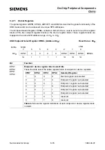
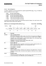
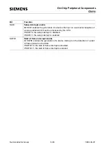
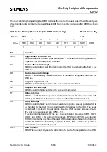
Control transfer always begin with a setup stage that transfers information to a target device,
defining the type of request being made to the USB device. The standard commands except the
“set_descriptor“ and “get_descriptor“ command are handled by the USB module automatically
without CPU interaction. If the command is not handled by the USB module automatically, a setup
interrupt (bit SUI is set) indicates the end of a setup phase. Additionally, the status and control bits
UBF, CBF and SOD are reset.
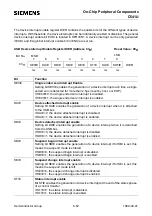
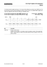
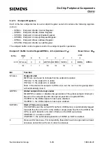
Since C541U only supports single device configuration and single interface, setting multiple device
configuration through “set_configuration” and setting alternate interface through “set_interface” to
the device will be ignored. In the case that the host sends multiple device configuration and/or
alternate interface, the device request value interrupt can be used to capture the events.
6.4.6.2
Data Stage
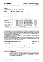
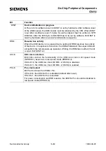
This stage is defined only for requests that require data transfers. The direction of this data stage is
always predicted to be from Host to Device (bit DIR is automatically cleared after the setup stage
occured). The first data packet may immediately be send from the Host to the control endpoint
according to this configuration of bit DIR, while NACK will be automatically returned from the Device
to the Host in case of USB read access.
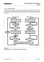
The configuration of bit DIR=0 predicts an USB write access, while an USB read access causes
automatically a NACK (no acknowledge) to be generated and the direction bit to be changed
(DIR=1, USB read access).
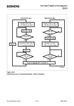
The direction of the next transfer can also be predicted under software control (bit SETWR is set)
to be an USB read access (DIR=1). This feature is used, if the direction of the data stage is known
and the data packet to be transferred from the CPU to the Host is set up before the next USB access
occured. Therefore, the direction bit must be changed under software control, to be able to transfer
the data packet within the first USB read access.
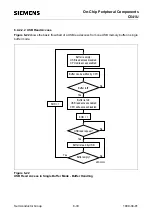
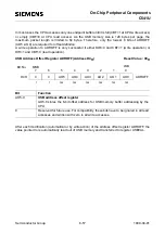
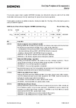
Status bit SOD is set under hardware control to indicate valid data to be read by CPU in case of USB
write access, or data to be written by CPU in case of USB read access.
6.4.6.3
Status Stage
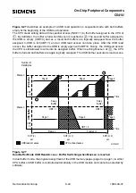
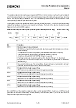
The status stage is always performed to report the result of the requested operation. A status stage
initiated by the Host, but not terminated according to the configuration of ESP (ESP=0) is indicated
by a status interrupt (bit STI is set). Bit ESP has to be set under software control to enable the
acknowledge of the status stage.
Содержание C541U
Страница 1: ... 8 LW 026 0LFURFRQWUROOHU 8VHU V 0DQXDO http www siem ens d Sem iconductor ...
Страница 7: ......
Страница 21: ...Semiconductor Group 2 6 1997 10 01 Fundamental Structure C541U ...
Страница 37: ...Semiconductor Group 4 6 1997 10 01 External Bus Interface C541U ...
Страница 133: ...Semiconductor Group 6 88 1999 04 01 On Chip Peripheral Components C541U ...
Страница 163: ...Semiconductor Group 8 8 1997 10 01 Fail Safe Mechanisms C541U ...
Страница 185: ...Semiconductor Group 10 14 1997 10 01 OTP Memory Operation C541U ...
Страница 192: ...Semiconductor Group 12 7 Index C541U ...

