Semiconductor Group
12-4
Index
C540U / C541U
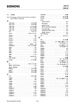
NOD2 . . . . . . . . . . . . . . . . . . . . . . . . . . 3-10
NOD3 . . . . . . . . . . . . . . . . . . . . . . . . . . 3-10
NOD4 . . . . . . . . . . . . . . . . . . . . . . . . . . 3-10
NODIE0 . . . . . . . . . . . . . . . . . . . . . . . . . 3-9
NODIE1 . . . . . . . . . . . . . . . . . . . . . . . . . 3-9
NODIE2 . . . . . . . . . . . . . . . . . . . . . . . . 3-10
NODIE3 . . . . . . . . . . . . . . . . . . . . . . . . 3-10
NODIE4 . . . . . . . . . . . . . . . . . . . . . . . . 3-10
NODIEn . . . . . . . . . . . . . . . . . . . . 6-70, 7-8
NODn . . . . . . . . . . . . . . . . . . . . . 6-72, 7-14
O
Oscillator operation . . . . . . . . . . . 5-6 to 5-8
External clock source . . . . . . . . . . . . . 5-8
On-chip oscillator circuitry. . . . . . . . . . 5-8
Recommended oscillator circuit . . . . . 5-7
Oscillator watchdog . . . . . . . . . . . 8-5 to 8-7
Behaviour at reset. . . . . . . . . . . . . . . . 5-3
Block diagram . . . . . . . . . . . . . . . . . . . 8-6
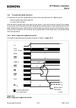
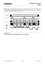
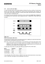
OTP memory operation . . . . . 10-1 to 10-13
Access mode selection . . . . . . . . . . . 10-6
Basic prog. mode selection. . . . . . . . 10-5
Lock bit access . . . . . . . . . . . . . . . . . 10-9
OTP memory protection levels . . . . . 10-9
OTP protection
Level 1 verifiy timimg. . . . . . . . . . 10-12
OTP verification example . . . . . . 10-13
Protection level 1. . . . . . . . . . . . . 10-12
Pin configuration
P-LCC-44 package . . . . . . . . . . . . 10-2
Pin definitions and functions . . 10-3, 10-4
Program/read operation . . . . . 10-7, 10-8
Programming mode . . . . . . . . . . . . . 10-1
Version byte access . . . . . . . . . . . . 10-11
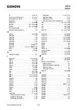
OV . . . . . . . . . . . . . . . . . . . . . . . . . 2-3, 3-7
OWDS . . . . . . . . . . . . . . . . . . . . . . 3-7, 8-3
P
P . . . . . . . . . . . . . . . . . . . . . . . . . . . 2-3, 3-7
P0 . . . . . . . . . . . . . . . . . . . . . . . . . . 3-4, 3-6
P1 . . . . . . . . . . . . . . . . . . . . . . . . . . 3-4, 3-6
P2 . . . . . . . . . . . . . . . . . . . . . . . . . . 3-4, 3-6
P3 . . . . . . . . . . . . . . . . . . . . . . . . . . 3-4, 3-7
PAGE0 . . . . . . . . . . . . . . . . . . . . . . . . . . 3-9
PAGE1 . . . . . . . . . . . . . . . . . . . . . . . . . . 3-9
PAGE2 . . . . . . . . . . . . . . . . . . . . . . . . . 3-10
PAGE3 . . . . . . . . . . . . . . . . . . . . . . . . . 3-10
PAGE4 . . . . . . . . . . . . . . . . . . . . . . . . . 3-10
PAGEn . . . . . . . . . . . . . . . . . . . . . . . . . 6-74
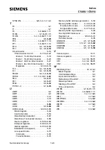
Parallel I/O . . . . . . . . . . . . . . . . . 6-1 to 6-14
PCLK . . . . . . . . . . . . . . . . . . . . . . 3-9, 6-60
PCON . . . . . . . . . . . . . . . . . . . 3-5, 3-6, 9-2
PCON1 . . . . . . . . . . . . . . . . . . 3-5, 3-6, 9-2
PDE . . . . . . . . . . . . . . . . . . . . . . . . 3-6, 9-2
PDS . . . . . . . . . . . . . . . . . . . . . . . . 3-6, 9-2
Pin configuration . . . . . . . . . . . . . . . . . . 1-4
P-LCC-44 package. . . . . . . . . . . . . . . 1-4
Pin definitions and functions . . . . 1-5 to 1-8
Ports . . . . . . . . . . . . . . . . . . . . . 6-1 to 6-14
Alternate functions . . . . . . . . 6-10 to 6-11
Port loading and interfacing . . . . . . . 6-13
Port timing . . . . . . . . . . . . . . . . . . . . 6-12
Quasi-bidirectional port structure
Basic circuitry of port 1 to 3 . . . . . . 6-3
Output driver circuitry . . . . . . . . . . . 6-4
Port 0 circuitry. . . . . . . . . . . . . . . . . 6-8
Port 0/2 as address/data bus . . . . . 6-9
SSC pins at port 1 . . . . . . . . . . . . . .6-6
Read-modify-write function . . . . . . . 6-14
Power saving modes . . . . . . . . . . 9-1 to 9-8
Behaviour of external pins . . . . . . . . . 9-3
Idle mode . . . . . . . . . . . . . . . . . 9-3 to 9-4
Power down mode . . . . . . . . . . 9-5 to 9-8
Entering . . . . . . . . . . . . . . . . . . . . . 9-6
External wake-up timing . . . . . . . . . 9-7
Functionality . . . . . . . . . . . . . . . . . . 9-5
Termination. . . . . . . . . . . . . . . . . . . 9-7
PSEN signal. . . . . . . . . . . . . . . . . . . . . . 4-3
PSSC . . . . . . . . . . . . . . . . . . . . . . 3-7, 7-16
PSW. . . . . . . . . . . . . . . . . . . . . 2-3, 3-4, 3-7
PT0 . . . . . . . . . . . . . . . . . . . . . . . 3-7, 7-16
PT1 . . . . . . . . . . . . . . . . . . . . . . . 3-7, 7-16
PUDI . . . . . . . . . . . . . . . . . . . . . . 3-7, 7-16
PUEI . . . . . . . . . . . . . . . . . . . . . . 3-7, 7-16
PX0 . . . . . . . . . . . . . . . . . . . . . . . 3-7, 7-16
PX1 . . . . . . . . . . . . . . . . . . . . . . . 3-7, 7-16
R
RD . . . . . . . . . . . . . . . . . . . . . . . . . . . . . 3-7
Reset . . . . . . . . . . . . . . . . . . . . . . 5-1 to 5-5
Fast power-on reset . . . . . . . . . . . . . . 5-3
Hardware reset timing . . . . . . . . . . . . 5-5
of USB module . . . . . . . . . . . . . . . . . . 5-2
Power-on reset timing . . . . . . . . . . . . 5-4
Reset circuitries . . . . . . . . . . . . . . . . . 5-2
Содержание C541U
Страница 1: ... 8 LW 026 0LFURFRQWUROOHU 8VHU V 0DQXDO http www siem ens d Sem iconductor ...
Страница 7: ......
Страница 21: ...Semiconductor Group 2 6 1997 10 01 Fundamental Structure C541U ...
Страница 37: ...Semiconductor Group 4 6 1997 10 01 External Bus Interface C541U ...
Страница 133: ...Semiconductor Group 6 88 1999 04 01 On Chip Peripheral Components C541U ...
Страница 163: ...Semiconductor Group 8 8 1997 10 01 Fail Safe Mechanisms C541U ...
Страница 185: ...Semiconductor Group 10 14 1997 10 01 OTP Memory Operation C541U ...
Страница 192: ...Semiconductor Group 12 7 Index C541U ...


