Semiconductor Group
6-22
1999-04-01
On-Chip Peripheral Components
C541U
6.2.1.5
Mode 3
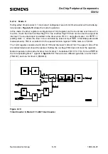
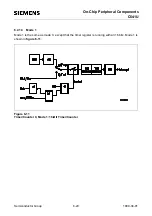
Mode 3 has different effects on timer 0 and timer 1. Timer 1 in mode 3 simply holds its count. The
effect is the same as setting TR1=0. Timer 0 in mode 3 establishes TL0 and TH0 as two seperate
counters. The logic for mode 3 on timer 0 is shown in figure 6-13. TL0 uses the timer 0 control bits:
C/T, Gate, TR0, INT0 and TF0. TH0 is locked into a timer function (counting machine cycles) and
takes over the use of TR1 and TF1 from timer 1. Thus, TH0 now controls the "timer 1" interrupt.
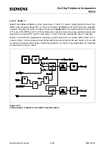
Mode 3 is provided for applications requiring an extra 8-bit timer or counter. When timer 0 is in
mode 3, timer 1 can be turned on and off by switching it out of and into its own mode 3, or can still
be used by the serial channel as a baud rate generator, or in fact, in any application not requiring
an interrupt from timer 1 itself.
Figure 6-13
Timer/Counter 0, Mode 3: Two 8-Bit Timers/Counters
TR1
Содержание C541U
Страница 1: ... 8 LW 026 0LFURFRQWUROOHU 8VHU V 0DQXDO http www siem ens d Sem iconductor ...
Страница 7: ......
Страница 21: ...Semiconductor Group 2 6 1997 10 01 Fundamental Structure C541U ...
Страница 37: ...Semiconductor Group 4 6 1997 10 01 External Bus Interface C541U ...
Страница 133: ...Semiconductor Group 6 88 1999 04 01 On Chip Peripheral Components C541U ...
Страница 163: ...Semiconductor Group 8 8 1997 10 01 Fail Safe Mechanisms C541U ...
Страница 185: ...Semiconductor Group 10 14 1997 10 01 OTP Memory Operation C541U ...
Страница 192: ...Semiconductor Group 12 7 Index C541U ...

