Semiconductor Group
6-7
1999-04-01
On-Chip Peripheral Components
C541U
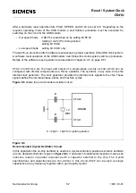
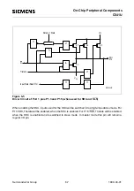
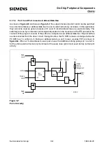
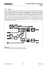
Figure 6-5
Driver Circuit of Port 1 pins P1.3 and P1.5 (when used for SRI and SLS)
When enabling the SSC, inputs used for the SSC will be switched into a high-impedance mode. For
P1.3/SRI, Tristate will be enabled, when the SSC is enabled. For P1.5/SLS, Tristate will be enabled,
when the SSC is enabled and is switched to slave mode. In master mode this pin will remain a
regular I/O pin.
MCS02433
=1
&
=1
=1
V
CC
Port
Pin
SS
V
Q
Tristate
Input Data (Read Pin)
Delay = 1 State
p1
p2
p3
n1
1<
_
1<
_
1<
_
Содержание C541U
Страница 1: ... 8 LW 026 0LFURFRQWUROOHU 8VHU V 0DQXDO http www siem ens d Sem iconductor ...
Страница 7: ......
Страница 21: ...Semiconductor Group 2 6 1997 10 01 Fundamental Structure C541U ...
Страница 37: ...Semiconductor Group 4 6 1997 10 01 External Bus Interface C541U ...
Страница 133: ...Semiconductor Group 6 88 1999 04 01 On Chip Peripheral Components C541U ...
Страница 163: ...Semiconductor Group 8 8 1997 10 01 Fail Safe Mechanisms C541U ...
Страница 185: ...Semiconductor Group 10 14 1997 10 01 OTP Memory Operation C541U ...
Страница 192: ...Semiconductor Group 12 7 Index C541U ...

