VLT
®
8000 AQUA
■
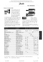
Analog/digital outputs
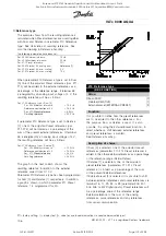
The two analog/digital outputs (terminals 42 and 45)
can be programmed to show the present status
or a process value such as 0 - f
MAX
.
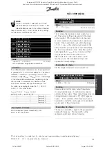
If the AFD is used as a digital output, it gives the
present status by means of 0 or 24 V DC. If the
analoge output is used for giving a process value,
there is a choice of three types of output signals:
0-20 mA, 4-20 mA or 0-32000 pulses
(depending on the value set in parameter 322
Terminal
45, output, pulse scaling
. If the output is used as
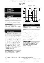
a voltage output (0-10 V), a pull-down resistor of
470
(max. 500
) should be fitted to terminal 39
(common for analog/digital outputs). If the output is
used as a current output, the resulting impedance of
the connected equipment should not exceed 500
.
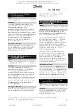
Outputs
terminal no.
42
45
parameter
319
321
Value:
No function (NO FUNCTION)
[0]
[0]
Drive ready (READY)
[1]
[1]
Standby (ENABLED & NO WARNING)
[2]
[2]
Running (RUNNING)
[3]
[3]
Running at ref. value (RUNNING AT REFERENCE)
[4]
[4]
Running, no warning (RUNNING NO WARNING)
[5]
[5]
Local reference active (DRIVE IN LOCAL REF.)
[6]
[6]
Remote references active (DRIVE IN REMOTE REF.)
[7]
[7]
Alarm (ALARM)
[8]
[8]
Alarm or warning (ALARM OR WARNING)
[9]
[9]
No alarm (NO ALARM)
[10]
[10]
Current limit (CURRENT LIMIT)
[11]
[11]
Safety interlock (SAFETY INTERLOCK)
[12]
[12]
Start command active (START SIGNAL APPLIED)
[13]
[13]
Reversing (REVERSE OPERATION)
[14]
[14]
Thermal warning (THERMAL WARNING)
[15]
[15]
Hand mode active (DRIVE IN HAND MODE)
[16]
[16]
Auto mode active (DRIVE IN AUTO MODE)
[17]
[17]
Sleep mode (SLEEP MODE)
[18]
[18]
Output frequency lower than f
LOW
parameter 223 (F OUT < F LOW)
[19]
[19]
Output frequency higher than f
HIGH
parameter 224 (F OUT > F HIGH)
[20]
[20]
Out of frequency range (FREQ. RANGE WARN.)
[21]
[21]
Output current lower than I
LOW
parameter 221 (I OUT < I LOW)
[22]
[22]
Output current higher than I
HIGH
parameter 222 (I OUT > I HIGH)
[23]
[23]
Out of current range (CURRENT RANGE WARN)
[24]
[24]
Out of feedback range (FEEDBACK RANGE WARN.)
[25]
[25]
Out of reference range (REFERENCE RANGE WARN)
[26]
[26]
Relay 123 (RELAY 123)
[27]
[27]
Mains imbalance (MAINS IMBALANCE)
[28]
[28]
Output frequency, 0 - f
MAX
⇒
0-20 mA (OUT. FREQ. 0-20 mA)
[29]
[29]
Output frequency, 0 - f
MAX
⇒
4-20 mA (OUT. FREQ. 4-20 mA)
[30]
✭
[30]
Output frequency (pulse sequence), 0 - f
MAX
⇒
0-32000 p (OUT. FREQ. PULSE)
[31]
[31]
External reference, Ref
MIN
- Ref
MAX
⇒
0-20 mA (EXT. REF. 0-20 mA)
[32]
[32]
External reference, Ref
MIN
- Ref
MAX
⇒
4-20 mA (EXTERNAL REF. 4-20 mA)
[33]
[33]
External reference (pulse sequence), Ref
MIN
- Ref
MAX
⇒
0-32000 p (EXTERNAL REF. PULSE)
[34]
[34]
Feedback, FB
MIN
- FB
MAX
⇒
0-20 mA (FEEDBACK 0-20 mA)
[35]
[35]
Feedback, FB
MIN
- FB
MAX
⇒
4-20 mA (FEEDBACK 4-20 mA)
[36]
[36]
Feedback (pulse sequence), FB
MIN
- FB
MAX
⇒
0 - 32000 p (FEEDBACK PULSE)
[37]
[37]
Output current, 0 - I
MAX
⇒
0-20 mA (MOTOR CUR. 0- 20 mA)
[38]
[38]
Output current, 0 - I
MAX
⇒
4-20 mA (MOTOR CUR. 4- 20 mA)
✭
[39]
[39]
Output current (pulse sequence), 0 - I
MAX
⇒
0 - 32000 p (MOTOR CUR. PULSE)
[40]
[40]
Output power, 0 - P
NOM
⇒
0-20 mA (MOTOR POWER 0-20 mA)
[41]
[41]
Output power, 0 - P
NOM
⇒
4-20 mA (MOTOR POWER 4-20 mA)
[42]
[42]
Output power (pulse sequence), 0 - P
NOM
⇒
0- 32000 p (MOTOR POWER PULSE)
[43]
[43]
Bus control, 0.0-100.0%
⇒
0-20 mA (BUS CONTROL 0-20 MA)
[44]
[44]
Bus control, 0.0-100.0%
⇒
4-20 mA (BUS CONTROL 4-20 MA)
[45]
[45]
Bus control (pulse sequence), 0.0-100.0%
⇒
0 - 32.000 Pulses (BUS CONTROL PULS)
[46]
[46]
Motor alteration (MOTOR ALTERATION)
[50]
[50]
✭
= factory setting. () = display text [] = value for use in communication via serial communication port
MG.80.A7.22 - VLT is a registered Danfoss trademark
120
Rosewood STP ST42 General (Operation and Maintenance Manual - Part 4:
Section 6.3 Manufacturers Manuals 6.3.33 Danfoss VLT Aquadrive 8000) Vendor Manual
QP Id: VM207
Active: 03/09/2013
Page 126 of 208

