VLT
®
8000 AQUA
120 Load compensation at high speed
(LOAD COMP HI SPD)
Value:
0 - 300 %
✭
100 %
Function:
This parameter enables compensation of voltage in
relation to load when the motor is running at high speed.
Description of choice:
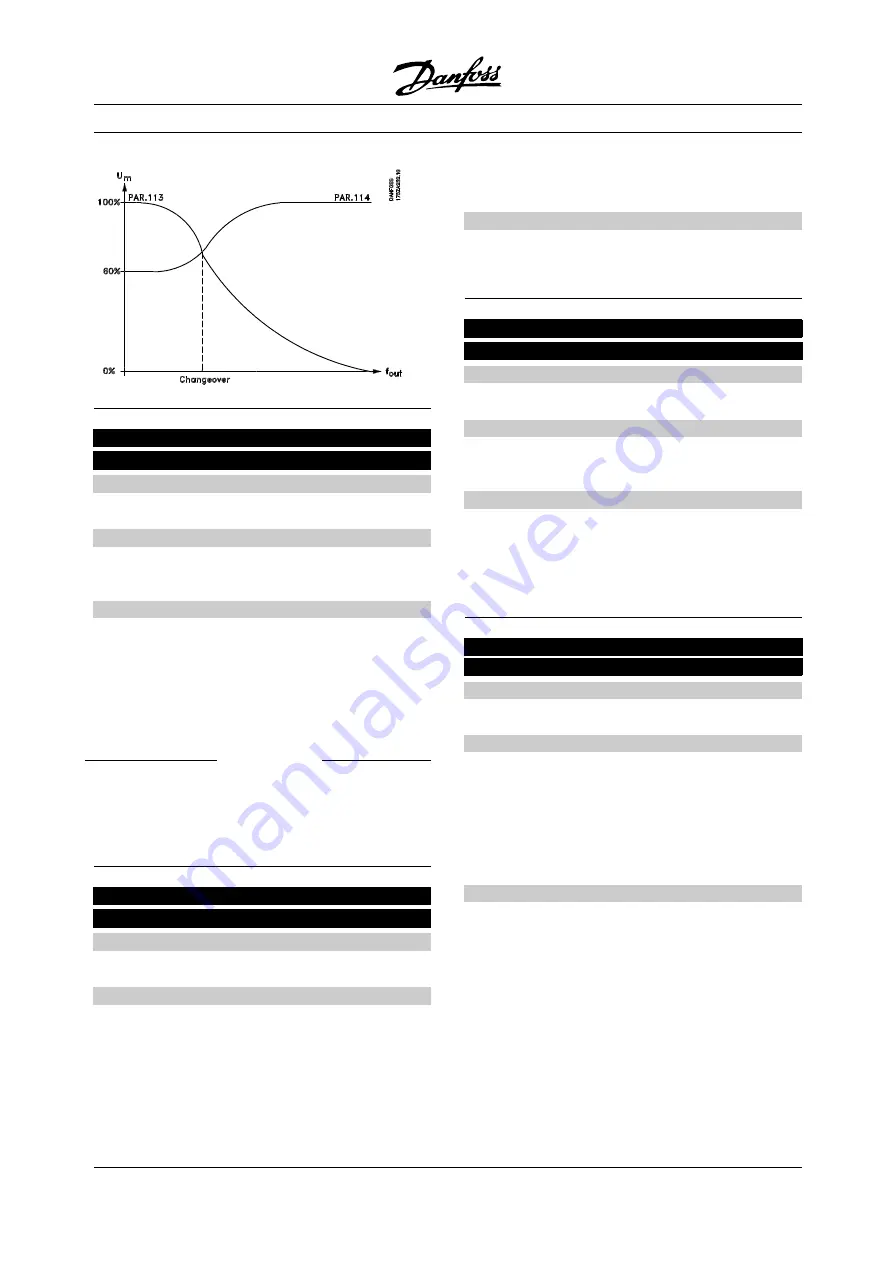
In
Load compensation at high speed
it is possible
to compensate for the load from the frequency
where
Load compensation at low speed
stopped
working to max.frequency.
This function is active for:
Motor size
Change-over
0.5 kW - 7.5 kW
>10 Hz
11 kW - 45 kW
>5 Hz
55 kW - 355 kW
>3-4 Hz
121 Slip compensation
(SLIP COMPENSAT.)
Value:
-500 - 500 %
✭
100 %
Function:
Slip compensation is calculated automatically, i.e. on
the basis of the rated motor speed n
M,N
.
In parameter 121, slip compensation can be
adjusted in detail, which compensates for
tolerances in the value of n
M,N
.
This function is not active together with
Variable
torque
(parameter 101 - variable torque graphs),
Torque control, Speed feedback
and
Special
motor characteristics.
Description of choice:
Enter a %-value of the rated motor frequency
(parameter 104).
122 Slip compensation time constant
(SLIP TIME CONST.)
Value:
0.05 - 5.00 sec.
✭
0.50 sec.
Function:
This parameter determines the slip compensation
reaction speed.
Description of choice:
A high value results in slow reaction. Conversely,
a low value results in quick reaction.
If low-frequency resonance problems are encountered,
the time set must be longer.
123 Stator resistance
(STATOR RESIST)
Value:
✭
Depends on the choice of motor
Function:
After setting motor data in parameters 102-106, a
number of adjustments of various parameters are
made automatically, including the stator resistance
R
S
. A manually entered R
S
must apply to a cold
motor. The shaft performance can be improved by
fine-tuning R
S
and X
S
, see procedure below.
Description of choice:
R
S
can be set as follows:
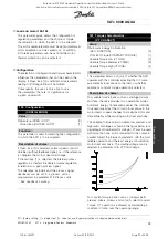
1. Automatic motor adaptation, where the AFD
actually tests the motor to determine this value.
All compensations are reset to 100%.
2. The values are stated by the motor supplier.
3. The values are obtained by means of
manual measurements:
-
R
S
can be calculated by measuring the
resistance R
PHASE-to-PHASE
between two phase
terminals. If R
PHASE-to-PHASE
is lower than 1-2 ohm
(typically motors > 4 (5.4 HP) - 5.5 kW (7.4 HP), 400
✭
= factory setting. () = display text [] = value for use in communication via serial communication port
MG.80.A7.22 - VLT is a registered Danfoss trademark
100
Rosewood STP ST42 General (Operation and Maintenance Manual - Part 4:
Section 6.3 Manufacturers Manuals 6.3.33 Danfoss VLT Aquadrive 8000) Vendor Manual
QP Id: VM207
Active: 03/09/2013
Page 106 of 208

