VLT
®
8000 AQUA
Programming
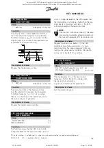
This function is only active if
Freeze reference
or
Freeze output
has been selected.
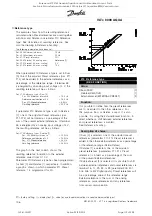
As long as there is a logic "1" on the terminal selected
for
Speed up
, the reference or the output frequency will
increase by the
Ramp-up time
set in parameter 206.
As long as there is a logic "1" on the terminal
selected for
Speed down
, the reference or the
output frequency will decrease by the
Ramp-down
time
set in parameter 207.
Pulses (logic "1" minimum high for 3 ms and a
minimum pause of 3 ms) will lead to a change of
speed of 0.1% (reference) or 0.1 Hz (output frequency).
Example:
Terminal
Terminal
Freeze ref./
(16)
(17)
Freeze output
No speed
change
0
0
1
Speed down
0
1
1
Speed up
1
0
1
Speed down
1
1
1
The speed reference, frozen via the control panel,
can be changed even if the adjustable frequency drive
has stopped. In addition, the frozen reference will
be remembered in case of an AC line failure.
Run permissive.
There must be an active start
signal via the terminal, where
Run permissive
has
been programmed, before a start command can be
accepted.
Run permissive
has a logic ‘AND
’
function
related to Start (terminal 18, parameter 302
Terminal
18, Digital input
), which means that in order to start
the motor, both conditions must be fulfilled. If
Run
permissive
is programmed on several terminals,
Run
permissive
must only be logic "1" on one of the
terminals for the function to be carried out.
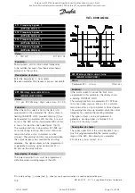
Jog
is used to override the output frequency to
the frequency set in parameter 209
Jog frequency
and issue a start command. If local reference is
active, the adjustable frequency drive will always
be in
Open loop
[0], regardless of the selection
made in parameter 100
Configuration
.
Jog is not active if a stop command has
been given via terminal 27.
Data change lock
is selected if data changes to
parameters are not to be made via the control
unit; however, it will still be possible to carry
out data changes via the bus.
Pulse reference
is selected if a pulse sequence
(frequency) is selected as a reference signal. 0 Hz
corresponds to Ref
MIN
, parameter 204
Minimum
reference, Ref
MIN
. The frequency set in parameter
327
Pulse reference, max. frequency
corresponds to
parameter 205
Maximum reference, Ref
MAX
.
Pulse feedback
is selected if a pulse sequence
(frequency) is selected as a feedback signal.
Parameter 328
Pulse feedback, max. frequency
is
where the maximum frequency for pulse feedback is set.
Hand start
is selected if the adjustable frequency drive
is to be controlled by means of an external hand/off
or H-O-A switch. A logic ‘1
’
(Hand start active) will
mean that the adjustable frequency drive starts the
motor. A logic "0" means that the connected motor
stops. The adjustable frequency drive will then be in
OFF/STOP mode, unless there is an active
Auto start
signal
. See also the description in
Local control
.
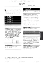
NOTE
An active Hand and Auto signal via the digital
inputs will have higher priority than the [HAND
START]-[AUTO START] control keys.
Auto start
is selected if the adjustable frequency
drive is to be controlled via an external auto/off or
H-O-A switch. A logic
’
1
’
will place the adjustable
frequency drive in auto mode allowing a start signal
on the control terminals or the serial communication
port. If
Auto start
and
Hand start
are active at the
same time on the control terminals,
Auto start
will
have the highest priority. If
Auto start
and
Hand start
are not active, the connected motor will stop and the
adjustable frequency drive will then be in OFF/STOP
mode. See also the description in
Local control
.
Latched start
will start the motor if a pulse is
applied for a minimum of 3 ms, provided there
is no stop command active. The motor will stop
if
Stop Inverse
is briefly activated.
Off stop
is used for stopping the connected motor.
The stop will be effected in accordance with the
selected ramp (par. 206 and 207).
Stop inverse
is activated by interrupting the voltage
to the terminal. This means that if the terminal
has no voltage, the motor cannot run. The stop
✭
= factory setting. () = display text [] = value for use in communication via serial communication port
MG.80.A7.22 - VLT is a registered Danfoss trademark
115
Rosewood STP ST42 General (Operation and Maintenance Manual - Part 4:
Section 6.3 Manufacturers Manuals 6.3.33 Danfoss VLT Aquadrive 8000) Vendor Manual
QP Id: VM207
Active: 03/09/2013
Page 121 of 208

