VLT
®
8000 AQUA
■
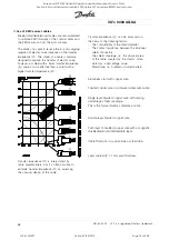
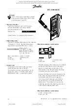
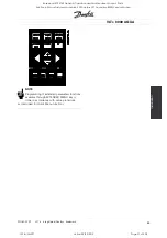
Control unit LCP
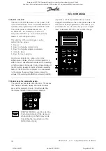
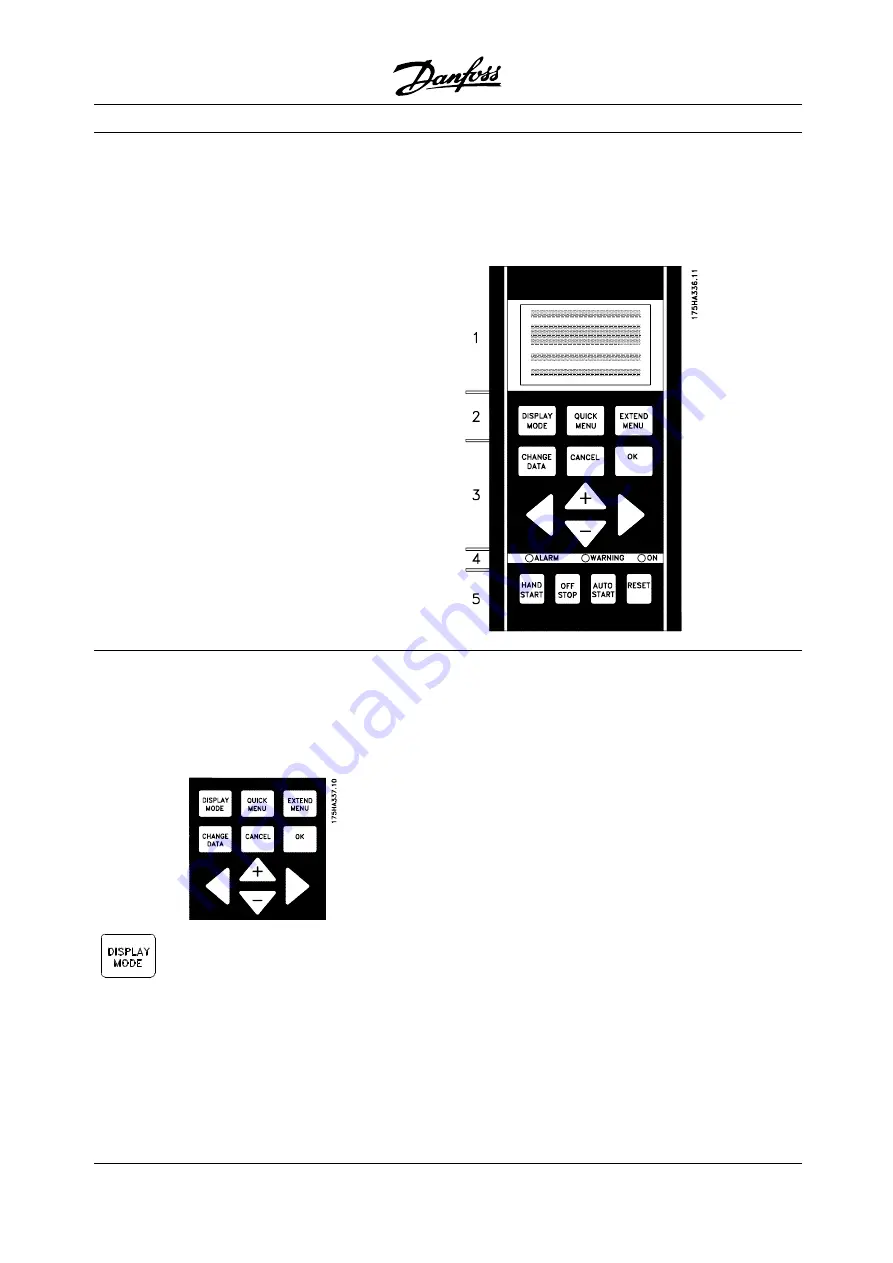
The front of the AFD features a control panel - LCP
(Local Control Panel). This is a complete interface for
operation and programming of the VLT 8000 AQUA.
The control panel is detachable and can - as
an alternative - be installed up to 3m/10 ft
away from the AFD, e.g. on the front panel, by
means of a mounting kit option.
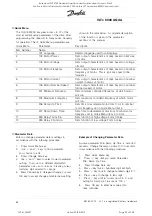
The functions of the control panel can be
divided into five groups:
1. Display
2. Keys for changing display mode
3. Keys for changing program parameters
4. Indicator lamps
5. Keys for local operation.
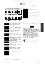
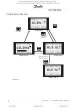
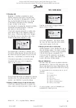
All data are indicated by means of a 4-line
alpha-numeric display, which, in normal operation, is
able to show 4 operating data values and 3 operating
condition values continuously. During programming, all
the information required for quick, effective parameter
Setup of the AFD will be displayed. As a supplement
to the display, there are three indicator lamps for
voltage (ON), warning (WARNING) and alarm (ALARM),
respectively. All AFD parameter Setups can be
changed immediately via the control panel, unless this
function has been programmed to be
Locked
[1] via
parameter 016
Lock for data change
or via a digital
input, parameters 300-307
Lock for data change
.
■
Control keys for parameter setup
The control keys are divided into functions. This means
that the keys between display and indicator lamps
are used for parameter Setup, including selecting
the display indication during normal operation.
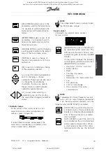
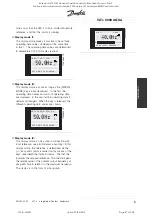
[DISPLAY MODE] is used for selecting
the indication mode of the display or
when returning to the Display mode
from either the Quick menu or the
Extend menu mode.
MG.80.A7.22 - VLT is a registered Danfoss trademark
78
Rosewood STP ST42 General (Operation and Maintenance Manual - Part 4:
Section 6.3 Manufacturers Manuals 6.3.33 Danfoss VLT Aquadrive 8000) Vendor Manual
QP Id: VM207
Active: 03/09/2013
Page 84 of 208

