Connecting your equipment
03
40
En
Operating other Pioneer components
with this unit’s sensor
Many Pionee
r
components have
SR CONTROL
jacks
which can be used to link components togethe
r
so that
you can use just the
r
emote senso
r
of one component.
When you use a
r
emote cont
r
ol, the cont
r
ol signal is
passed along the chain to the app
r
op
r
iate component.
1
Important
• Note that if you use this featu
r
e,
make sure that you
also have at least one set of analog audio, video or
HDMI jacks connected
to anothe
r
component fo
r
g
r
ounding pu
r
poses.
1
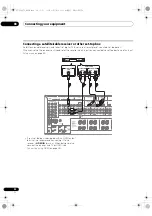
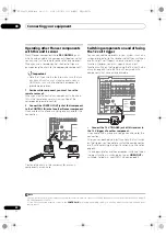
Decide which component you want to use the
remote sensor of.
When you want to cont
r
ol any component in the chain,
this is the
r
emote senso
r
at which you’ll point the
co
rr
esponding
r
emote cont
r
ol.
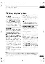
2
Connect the CONTROL OUT jack of that component
to the CONTROL IN jack of another Pioneer component.
Use a cable with a mono mini-plug on each end fo
r
the
connection.
Continue the chain in the same way fo
r
as many
components as you have.
Switching components on and off using
the 12 volt trigger
You can connect components in you
r
system (such as a
sc
r
een o
r
p
r
ojecto
r
) to this
r
eceive
r
so that they switch on
o
r
off using 12 volt t
r
igge
r
s when you select an input
function. Howeve
r
, you must specify which input
functions switch on the t
r
igge
r
using the
The Input Setup
menu
on page 45. Note that this will only wo
r
k with
components that have a standby mode.
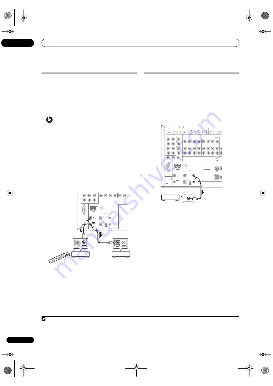
•
Connect the 12 V TRIGGER jack of this receiver to
the 12 V trigger of another component.
Use a cable with a mono mini-plug on each end fo
r
the
connection.
Afte
r
you’ve specified the input functions that will switch
on the t
r
igge
r
, you’ll be able to switch the component on
o
r
off just by p
r
essing the input function(s) you’ve set on
page 45.
It is also possible to have the component switch not when
the input function is switched, but when
HDMI OUT
is
switched. Fo
r
details, see
HDMI Setup
on page 68.
Note
1 • If you want to cont
r
ol all you
r
components using this
r
eceive
r
’s
r
emote cont
r
ol, see
Setting the remote to control other components
on page 79
(SC-LX83)/page 92 (SC-LX73).
• If you have connected a
r
emote cont
r
ol to the
CONTROL IN
jack (using a mini-plug cable), you won’t be able to cont
r
ol this unit using the
r
emote senso
r
.
CONTROL
IN
OUT
RS-232C
MONITOR OUT
ZONE 2 OUT
Y
ANTENNA
FM UNBAL 75
AM LOOP
P
R
P
B
CU-RF100
IR
12 V
TRIGGER
IN
IN
OUT
1
2
1
2
(OUTPUT
12 V
TOTAL
150 mA MAX)
(OUTPUT 5 V
150 mA MAX)
SPEAKERS
CONTROL
IN
OUT
IN
OUT
CONTROL
12 V
TRIGGER
1
2
(OUTPUT
12 V
TOTAL
150 mA MAX)
RS-232C
HDMI
ASSIGNABLE
COMPONENT VIDEO
ASSIGNABLE
MONITOR OUT
ZONE 2 OUT
IN
Y
ANTENNA
FM UNBAL 75
AM LOOP
CD
IN
VIDE
MONITOR
OUT
ZONE2
OUT
ZONE3
OUT
DVD
IN
TV/SAT
IN
VIDEO
IN
DVR/BDR
PHONO
IN
OUT
IN
P
R
P
B
1
IN
BD
IN
1
IN
2
IN
3
OUT 1
(CONTROL)
OUT
1
4
(DVD)
IN
2
(DVR/BDR)
IN
3
(VIDEO)
CONTROL
CU-RF100
IR
IN
IN
IN
OUT
OUT
1
2
IN
4
(OUTPUT 5 V
150 mA MAX)
SPEAKERS
SIGNAL
GND
R
FRONT HEIGHT/W
SEE INSTRUCTION
MANUAL
SELECTABLE
CAUTION:
SPEAKER IMPEDANCE
6
Ω
- 16
Ω
.
12 V TRIGGER
INPUT
SC-LX83_73_DLPW.book 40 ページ 2010年5月19日 水曜日 午後2時7分

