background image


219 


d

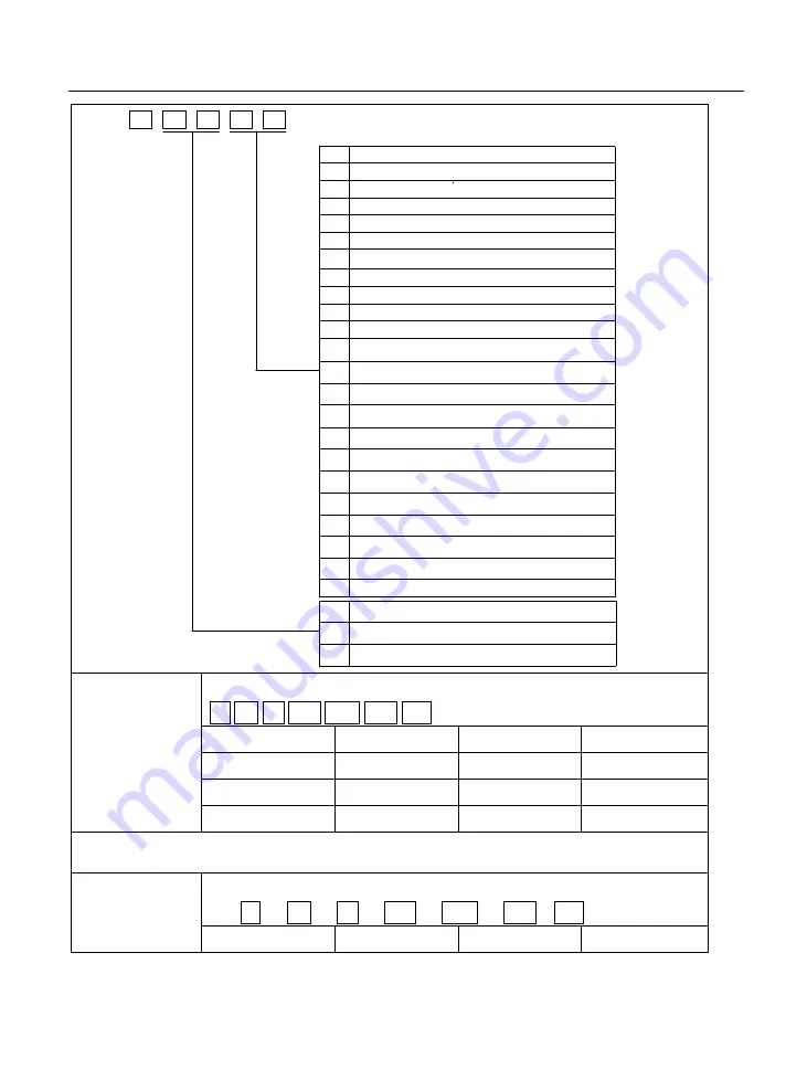
Control mode setting

X

Position pulse mode

Internal register torque mode

1

Internal register speed mode

Reserved 

0

4

3

2

5

Internal register position mode

6

7

8

9

10

11

12

13

14

15

16

18

19

20

Mix mode of internal register speed and position pulse 

Mix mode of internal register speed and internal register torque

Mix mode of internal register speed and internal register position

Mix mode of internal register torque and position pulse

Mix mode of position pulse and internal register position

17

Mix mode of internal register torque and internal register position

Y

0

1

Clockwise as viewed from servo motor shaft

Counterclockwise as viewed from  servo motor shaft

Motor forward direction setting

Reserved 

Reserved 

Reserved 

Reserved 

Reserved 

Reserved 

Reserved 

Reserved 

Reserved 

Reserved 

21

Bus mode


Sub-index 04h


Encoder frequency-division numbers 

PP PV PT CSP CSV CST HM 

Setting Range 

Setting Unit 

Mfr’s Value 

Effect 

1

65535 

N/A


— 

immediate 

Function code 

Mapping o 

Data type 

Accessibility 

Po003


UINT16 

RW 

Po003 is used to set frequency-division numbers for each phase.   
The entry-into-effect time is 100ms.


Sub-index 06h


Encoder pulse frequency-division numbers denominator


      PP      PV      PT      CSP      CSV      CST    HM 

Setting Range 

Setting Unit 

Mfr’s Value 

Effect 

Содержание FL-20-C Series

Страница 1: ......

Страница 2: ... your valuable comment and suggestion Our company is committed to the improvement of products and function upgrade The content of user manual could be amended at any time without prior notice The latest and detailed user manual will be launched in corporate website Unpacking Inspection Please check as below carefully when unpacking Item to check Description Check if arrived goods are in complete a...

Страница 3: ... result in severe consequence sometimes The significance of identifier in the drive case as below High voltage electrical shock hazard Heat surface do not touch IEC STANDARD IEC EN 61800 5 1 2007 Adjustable speed electrical power drive systems safety requirements IEC EN 61800 3 2004 A1 2012 Adjustable speed electrical power drive system Part 3 EMC product standard including specific test methods A...

Страница 4: ...me industrial Ethernet standard OD Object dictionary INIT EtherCAT state machine Initialization state PREOP EtherCAT state machine Pre operation state SAFEOP EtherCAT state machine Safe operation state OP EtherCAT state machine Operation state SyncManager Synchronous manager control the access of application storage area SDO Service data object PDO Process data object TXPDO Transmit process data R...

Страница 5: ...n signal outputs without backslash means that the output side is always on it is off only when signal outputs 3 Others NC Not connected N A No unit XML File Configuration Instruction 1 Please use proper XML file to configure or install on the EtherCAT master before using FL20 C series servo slave to connect to the EtherCAT master 2 The version of XML file can be identified by servo parameter So 60...

Страница 6: ...LATION 28 3 1 SERVO DRIVE INSTALLATION 28 3 2 INSTALLATION OF SERVO MOTOR 34 IV WIRING 42 4 1 MAIN CIRCUIT WIRING 44 4 2 ENCODER WIRING 51 4 3 INPUT OUTPUT SIGNAL WIRING 55 4 4 WIRING FOR SERVO DRIVE AND SERVO MOTOR 69 V KEYPAD OPERATION AND PARAMETERS 74 5 1 KEYPAD OPERATION 74 5 2 PANEL DISPLAY 75 5 3 KEYPAD OPERATING PROCEDURE 78 VI COMMUNICATION FUNCTION INTRODUCTION 82 6 1 ETHERCAT COMMUNICAT...

Страница 7: ...35 7 2 1 CONTROL WORD 6040H 138 7 2 2 STATUS WORD 6041H 139 7 3 PROFILE POSITION MODE PP 140 7 3 1 RELATED OBJECTS 140 7 3 2 RELATED FUNCTIONS 142 7 3 3 PATH GENERATOR 142 7 3 4 RECOMMENDED CONFIGURATION 145 7 4 PROFILE VELOCITY MODE PV 145 7 4 1 RELATED OBJECTS 145 7 4 2 RELATED FUNCTIONS 147 7 4 3 RECOMMENDED CONFIGURATION 147 7 5 PROFILE TORQUE MODE PT 147 7 5 1 RELATED OBJECTS 148 7 5 2 RELATE...

Страница 8: ...1 8 2 COMMUNICATION PARAMETER 1000H 1FFFH 212 8 3 MANUFACTURER DEFINED PARAMETERS 2125 8 4 PARAMETERS DEFINED BY SUB PROTOCOL 6000H 265 IX ADJUSTMENTS 277 9 1 SUMMARY 277 9 2 INERTIA IDENTIFICATION 278 9 2 1 OFFLINE IDENTIFICATION 278 9 2 2 ONLINE INERTIA IDENTIFICATION 281 9 3 GAIN ADJUSTMENT 282 9 3 1 SUMMARY 282 9 3 2 AUTOMATIC GAIN ADJUSTMENT 283 9 3 3 MANUAL GAIN ADJUSTMENT 284 9 3 4 GAIN SWI...

Страница 9: ...302 11 1 ENCODER CABLE SELECTION 302 11 1 1 ABSOLUTE ENCODER CABLE 302 11 1 2 INCREMENTAL ENCODER CABLE 303 11 1 3 RESOLVER ENCODER CABLE 304 11 2 CONTROL CABLE 304 11 3 POWER CABLE 304 11 4 SHIELDED NETWORK CABLE 305 11 5 OTHER CABLE 306 11 6 MOTOR AND MATCHED CABLE 307 ...

Страница 10: ...e do not modify max speed value Po002 Or machinery may damage or human injury occurs Within a period time after power on and off do not touch cooling fin external braking unit and servo motor because the temperature could be very high which may cause scald Never touch the rotating part when servo motor running Put servo motor in the status that can be emergency stop anytime when running installed ...

Страница 11: ...ation with more dust dirt salts and metal dust Location subjects to drips of water oil and drug location that vibration or shock can be transferred to subject Do not place any load exceeding the limit specified on the packing box Do not hold the product by the cables or motor shaft when transporting it 1 3 Installation Do not install the product in the environment of water corrosive gases inflamma...

Страница 12: ...cable and the maximum length is 15m for encoder cable Take appropriate countermeasures to potential interference when using the servo system in following locations Locations subjects to static electricity or other forms of noise Locations subjects to strong electromagnetic fields and magnetic fields Locations subjects to possible exposure to radioactivity Repair or maintain servo drive only after ...

Страница 13: ... 5 kW 11 kW 15 kW 18 kW 22 kW 30 kW 37 kW Voltage S2 T2 T3 1 phase220V 3 phase220V 3 phase400V Structure size W H D Brake type M1 M2 M3 M3 5 5kW MM4 M4 M5 M6 48 175 195 75 175 195 100 203 218 100 203 218 150 336 203 185 380 215 210 420 215 268 4 498 234 B3 no brake B1 B3 B1 B3 B1 B1 no brake B1 no brake B1 no brake B1 no brake Communication Modbus Internal EtherCAT F5 FeedbackType D2 D5 D51 D52 D7...

Страница 14: ...put terminal AC input terminal of main circuit power supply Refer to 4 1 Main circuit wiring Control power input terminal AC input terminal of control power supply Refer to 4 1 Main circuit wiring Servo motor terminal Connected to the driving cable of servo motor Refer to 4 4 2 Main circuit wiring Braking resistor terminal Built in or external braking terminals Refer to 7 1 7 Energy loss brake Gro...

Страница 15: ...60Hz Control circuit power 1 phase 3 phase AC 220V 15 10 50 60Hz Brake mode External brake resistor Built in brake resistor b 380 400V servo drive Item M2 M3 MM4 M4 M5 M6 Drive model 102 152 202 302 452 552 752 113 153 183 223 303 373 Continuous output current Arms 3 3 5 6 0 8 0 10 0 12 0 20 23 32 38 44 60 75 Max output current Arms 8 4 9 8 16 19 2 28 33 56 64 80 95 110 150 187 Main circuit power ...

Страница 16: ... Other models Built in brake resistor Control feature Control type PMSM motor Response frequency PMSM servo 1 2KHz Baud rate 0 01 load 0 100 Speed fluctuation PMSM 0 01 VC load fluctuation 0 to 100 Speed ratio 1 10000 EtherCAT specification Communication protocol EtherCAT protocol Support service CoE PDO SDO Synchronous method DC distributed clock Physical layer 100BASE TX Transmission speed 100 M...

Страница 17: ...ratio 1 0 01 B A 100 2 Support 2 groups of electronic gear which can be selected or switchover by users Acceleration Deceleration The setting range of accel decel time is 1 30000ms from 0 accelerated to rated speed Communication 1 RS485 RS232 communication port is connected with PC to set control parameters and to monitor servo 2 Support EtherCAT bus Parameter setting Keypad Use 4 keys to set para...

Страница 18: ... A L M IN OUT EtherCAT Master Controller OR CAT5E类及以上 带屏蔽的网线 The price of GD50PIL120C6S is USD117 6 in stock 3 phase AC power supply Breaker EMI filter Contactor Input choke DC choke Braking resistor 24V power supply Electromagnetic brake relay always on Special use for servo motor with electromagnetic brake CAT5E and above shielded cable plan form Network interface Internet port remind IN OUT Pan...

Страница 19: ...al absolute type 17 bit Digital absolute 23 bit Resolver encoder Digital incremental 23 bit Fig 2 2 1 Servo motor naming rule for 180 flange and below 180 flange motor FM R 0110 E 17 D 6 E Servo Motor FM series Rotary Speed 15 17 20 1500rpm 1700rpm 2000rpm Rated Power 0075 0110 0180 7 5KW 11KW 18KW C D Shaft Type Optical axis Shaft with keyway E F Flange Size 200 flange 6 Bus Voltage 600V F L E Br...

Страница 20: ...for 180 flange and below 180 flange motor Magnetic filed angle PMSM 17 0110R6EEDFL Un 380V Tn 64N m Fan voltage 220V Pn 11kw Nn 1700 r min Code TH CI F IP54 In 23A Date FM Fig 2 2 4 Servo motor nameplate for 180 spigot and 250 spigot motor note 1 Please refer to the chapter of 3 2 4 servo motor dimension for flange dimension 2 For 180 spigot and 250 spigot motor they can be installed by flanged mo...

Страница 21: ...ated torque Rated current Rotation inertia W N m A 10 4 Kg m2 FMS series 3000r min FMSA 201 32 200 0 64 1 2 0 17 FMSA 401 32 400 1 27 2 8 0 29 FMSA 751 33 750 2 39 3 5 1 82 FMSA 102 33 1000 3 5 4 5 2 9 FMSA 122 35 1200 4 5 6 9 FMSA 152 37 1500 5 7 5 12 2 FMSA 182 35 1800 6 8 10 1 FMSA 232 37 2300 7 7 10 18 2 FMSA 302 37 3000 10 15 5 24 2 FMM series 2000 r min FMMA 801 35 800 4 3 5 6 9 FMMA 851 37 ...

Страница 22: ... 37 1000 10 4 5 24 2 FMLA 152 37 1500 14 3 7 34 9 FMLA 292 3A 2900 27 12 84 8 FMLA 372 3A 3700 35 16 119 5 2 380V motor model Motor modelnote Rated power Rated torque Rated current Rotation inertia W N m A 10 6 Kg m2 FMS series 3000 r min FMSA 751 63 750 2 39 2 1 82 FMSA 102 63 1000 3 5 3 2 9 FMSA 122 65 1200 4 4 6 9 FMSA 152 67 1500 5 5 12 2 FMSA 182 65 1800 6 6 10 1 FMSA 232 67 2300 7 7 7 18 2 F...

Страница 23: ...B 432 6A 4300 27 10 84 8 FMMB 552 6A 5500 35 12 5 119 5 FMMB 752 6A 7500 48 17 133 FML series 1000 r min FMLA 102 67 1000 10 3 24 2 FMLA 292 6A 2900 27 7 84 8 FMLA 372 6A 3700 35 9 119 5 3 Servo motor of 180 spigot and 250 spigot Motor modelnote Rated power Rated torque Rated current KW N m A FMM series 1500 r min FM15 0082 6EE FL 8 2 52 16 6 FM15 0100 6EE FL 10 64 20 7 FM15 0124 6EE FL 12 4 80 24...

Страница 24: ...6 185 74 FM20 0071 6FEDNL 7 1 34 14 5 FM20 0094 6EEDNL 9 4 45 18 8 FM20 0117 6EEDNL 11 7 56 24 4 FM20 0140F6EEDNL 14 67 28 6 Note represents shaft type and brake type please refer to the chapter of servo motor naming rule 2 3 Combination of servo drive and servo motor Combination of 220V servo motor and FL20 servo drive Motor modelnote Power Adaptable servodrive Note W 1 phase220V 3 phase 220V Fun...

Страница 25: ...MMB 152 37 1500 FL20 C182S2M2 FL20 C182T2M2 FMMB 232 37 2300 FL20 C302T2M3 FMMB 272 3A 2700 FMMB 302 3A 3000 FMMB 432 3A 4300 FL20 C452T2M3 FML series 1000r min FMLA 102 37 1000 FL20 C102S2M2 FL20 C102T2M2 FMLA 152 37 1500 FL20 C182S2M2 FL20 C182T2M2 FMLA 292 3A 2900 FL20 C302T2M3 FMLA 372 3A 3700 FL20 C452T2M3 Combination of 380V servo motor and FL20 servo drive Motor modelnote Power Adaptable se...

Страница 26: ...2 67 1500 FL20 C202T3M3 FMMB 232 67 2300 FMMB 302 67 3000 FL20 C302T3M3 FMMB 272 6A 2700 FMMB 302 6A 3000 FMMB 432 6A 4300 FL20 C452T3M3 FMMB 552 6A 5500 FL20 C552T3M3 FMMB 752 6A 7500 FL20 C752T3MM4 FML series 1000r min FMLA 102 67 1000 FL20 C152T3M2 FMLA 292 6A 2900 FL20 C302T3M3 FMLA 372 6A 3700 FL20 C452T3M3 FMM series 1500r min FM15 0082 6EE FL 8200 FL20 C752T3MM4 FM15 0100 6EE FL 10000 FL20 ...

Страница 27: ... 6EE FL 22000 FL20 C223T3M5 FM20 0250 6EE FL 25000 FL20 C303T3M6 FM20 0280 6EE FL 28000 FM20 0300 6EE FL 30000 FL20 C373T3M6 FM20 0360 6FE FL 36000 FM20 0071 6FEDNL 7100 FL20 C752T3MM4 FM20 0094 6EEDNL 9400 FM20 0117 6EEDNL 11700 FL20 C153T3M4 FM20 0140 6EEDNL 14000 Note 1 5 5 kw and above 5 5kw servo drive doesn t have dynamic brake M1 MM4 structure and above servodrive doesn t have built in resi...

Страница 28: ...ter bead coagulation Vibration Strength Below 0 5G 4 9m s2 10 60Hz Discontinuous IP rating IP20 Power system TN system Note Note TN system A power distribution system having one point directly earthed the exposed conductive parts of the installation being connected to that points by protective earth conductor 3 1 2 Installation precautions To make good effect of cooling circulation user needs to e...

Страница 29: ...aced on top to avoid the temperature rise Consult with supplier if smaller space need Fan Fan Fan Servo Drive Servo Drive Servo Drive 200mm 200mm 200mm 40mm 20mm 20mm 40mm 100mm 100mm 100mm CAT5E shielded cable Fig 3 1 2 min installation dimension for multiple drives installed 3 1 3 Servo drive dimension M1 structure dimension unit mm Fig 3 1 3 Servo drive structure size 1 ...

Страница 30: ...FL20 C Series 30 M2 structure dimension unit mm Fig 3 1 4 servo drive structure size 2 M3 structure dimension unit mm Fig 3 1 5 servo drive structure size 3 ...

Страница 31: ...FL20 C Series 31 MM4 structure dimension unit mm 8 ALM A Connected 1 Disconnected 0 Fig 3 1 6 Servo drive structure size 4 ...

Страница 32: ...FL20 C Series 32 M4 structure dimension unit mm Fig 3 1 7 Servo drive structure size 5 ...

Страница 33: ...FL20 C Series 33 M5 structure dimension unit mm Fig 3 1 8 Servo drive structure size 6 ...

Страница 34: ...nflammable gases or combustibles such as hydrogen sulfide chlorine ammonia sulphur gas chloridize gas acid soda and salt Select and use the servo motor with oil seal in a place with grinding fluid oil spray iron powder or cuttings Install the servo motor away from heat sources such as heating stove Never use the servo motor in an enclosed environment Working in the enclosed environment could resul...

Страница 35: ...aft end for the servo motor shaft with key slot Use methods such as friction coupling for servo motor shaft without key slot To avoid bearings bear strong impact of load use remover to assemble pulley Install protective cover or similar device on the rotation zone such as pulley Alignment Use coupler to align the servo motor shaft with the shaft of the equipment when connecting to the machinery Or...

Страница 36: ...rrect pin arrangement Do not exert force to connector which is made from resin When handling a servo motor with its cable connected do not exert force to the connector The connector may be damaged because of the stress 3 2 4 Servo motor dimension Dimension between shaft front face and flange face Flange lug height of motor face A A A A Dimension between shaft front face and shaft shoulder Toleranc...

Страница 37: ...r plug 7 core absolute encoder plug Outgoing cable length is600mm The dimension between shaft shoulder and motor front face flange termination is only reference it is forbidden to be used as datum reference If user needs this data please contact with Manufacturer Fig 3 2 2 Servo motor installation dimension Model L mm Weight Kg L mm With brake Remarks FMSA 751 3 192 2 8 231 The screw hole size M5 ...

Страница 38: ...e If user needs this data please contact with Manufacturer Dimension between shaft front face and shoulder Tolerance grade not noted refer to GB T 1804 2000 M Waterproof rubber cover of aviation plug Fig 3 2 3 Servo motor installation dimension Model L mm Weight kg L mm with brake Remarks FMSA 122 5 FMMA 801 5 250 6 5 290 The screw hole size M6 X 25 FMSA 182 5 FMMA 122 5 280 8 320 ...

Страница 39: ...lease contact with Manufacturer Waterproof rubber cover of aviation plug Tolerance grade not noted refer to GB T 1804 2000 M Fig 3 2 4 Servo motor installation dimension Model L mm Weight Kg L mm with brake Remarks FMMA 851 7 FMSA 152 7 FMMA 102 7 230 7 275 The screw hole size M6 X 25 FMMA 132 7 238 7 7 283 FMSA 232 7 FMMA 152 7 FMMB 122 7 251 8 296 FMSA 302 7 FMMA 202 7 FMMB 152 7 FMLA 102 7 274 ...

Страница 40: ...lation dimension Model L without brake mm Weight Kg L with brake mm L1 without brake mm L1 with brake mm Remarks FMMA 352 A FMMB 272 A 300 18 382 149 5 175 5 The screw hole size is M10 X 30 FMMA 452 A FMMB 302 A 320 20 402 149 5 175 5 FMMA 602 6A FMMB 432 A FMLA 292 A 332 23 414 149 5 175 5 FMMA 802 6A FMMB 552 A FMLA 372 A 370 29 452 149 5 175 5 FMMA 103 6A FMMB 752 A 416 36 498 149 5 175 5 Note ...

Страница 41: ...112 5 4 5 53 14 90 185 128 147 Base H1 H2 H3 H4 H5 M1 M2 E 124 200 224 12 200 254 278 F 160 240 294 13 266 356 396 T 100 C 68 84 96 130 147 160 196 220 275 330 380 428 481 52 64 80 102 118 135 152 185 225 270 307 324 385 Stand spigot E E E E E E E F F F F F F L4 mm 285 312 354 396 436 478 520 317 370 423 476 529 583 L5 mm 397 429 471 513 555 597 619 511 5 560 5 609 5 658 5 707 5 756 5 Motor rated ...

Страница 42: ...ase AC power supply Noise filter Lack phase detection Relay drive Fan circuit DC DC conversion DC DC Keypad panel Manual power ON Manual power OFF servo alarm RLY normally open contact Self locking normally open contact self lock contact charge indicator Drive circuit Energy loss brake circuit Interface circuit Firmware 1 2 Firmware CN1 MODBUS RJ45 BUS PC IPC PLC HMI etc Master station PLC support...

Страница 43: ... 工控 机 PC等 3 phase AC power supply Noise filter Manual power ON Manual power OFF Self locking normally open contact servo alarm RLY normally open contact self lock contact Fan circuit Keypad panel Lack phase detection Relay drive charge indicator Drive circuit Energy loss brake circuit Interface circuit Firmware 1 2 CN1 MODBUS PC IPC PLC HMI etc Master station PLC supported EtherCAT protocol IPC PC...

Страница 44: ... B1 and B2 N N DC reactor connecting terminals Terminals are shorted by default Connect DC reactor between both terminals when restraining power harmonic U V W Servo motor connection terminals Connect to servo motor Ground terminal The servo drive must be grounded 2 380V names and functions of main circuit wiring terminals Terminal Symbol Terminal Name Function R L1 S L2 T L3 Main circuit power in...

Страница 45: ... method 1 Strip off the wire skin for around 5 6cm 2 Use pull rod or slotted screwdriver with 3 0 3 5mm edge to open circle opening by pushing the upper openings of terminal connector 3 Insert the core of wire into the circle openings then loose the screwdriver or pull rod Press down Press down Fig 4 1 3 Main circuit terminals connection method FL20 series product divides into 220V and 380V voltag...

Страница 46: ...0V 制动电阻 输出 P B R L1S L2T L3 Brake resistor Output Fig 4 1 5 380V servo power terminals wiring diagram When using screw terminal for wiring if lug is needed dimension of screw terminal as below X Y screw Fig 4 1 6 main circuit terminals sketch diagram ...

Страница 47: ...exact shape in kind prevail Table 4 1 1 FL20 series servo screw terminals dimension table Structure Main circuit terminals X mm Y mm Screw Locked Torque Nm M3 9 9 13 0 M4 1 24 Max MM4 10 2 12 7 M4 1 46 M4 11 7 16 M6 2 5 M5 13 16 M5 2 0 M6 20 3 23 5 M8 2 8 ...

Страница 48: ...or P E FIL filter Manual power off Panel orientation Servo drive Fig 4 1 7 Typical wiring of 220V servo main circuit Instructions 1 Built in brake resistor is used by default B2 and B3 are shorted If external resistor is need remove the jumper between B2 and B3 then connect external resistor between B1 and B2 2 RLY Externally connected alarm signal output relay 3 KM1 contactor select connect or di...

Страница 49: ...output 显示 面板 方向 EtherCAT master station Panel orientation Fig 4 1 8 Typical wiring of 380V servo main circuit Instructions 1 Built in brake resistor is used by default B2 and B3 are shorted If external resistor is need remove the jumper between B2 and B3 then connect external resistor between B1 and B2 2 RLY Externally connected alarm signal output relay 3 KM1 contactor select connect or disconnec...

Страница 50: ...f Do not touch the power terminals within 5 minutes after power off Use grounding cable with the same cross sectional area as the power cable Ground the servo drive reliably Do not power on the servo drive when any screw of the terminal block or any cable becomes loose Otherwise fire hazards may occur Wiring operation should be performed by professionals To avoid electric shock user must wait for ...

Страница 51: ...use of short make sure that the shielded layer and grounding are connected reliably 4 2 1 Absolute encoder connector terminal layout CN2 Encoder Connector Terminal Layout is as shown in figure 4 2 1 1 2 3 4 5 6 7 8 9 Fig 4 2 1 Absolute encoder terminal layout Table 4 2 1 Encoder connector terminal name and function Terminal code Terminal abbreviation Signal name Function CN2 1 NC NO CONNECTION NO ...

Страница 52: ...ignal CN2 2 VCC 5V power output 5V power output CN2 3 KTY motor temperature sensor Motor temperature detection CN2 4 NC No connection No connection CN2 5 RE1 Resolver signal stimulus Connect to servo motor stimulus signal CN2 6 COS Resolver differential signal Connect to servo motor differential signal CN2 7 COS Resolver differential signal Connect to servo motor differential signal CN2 8 SIN Reso...

Страница 53: ...ncoder Z phase CN2 4 B Encoder B phase input Connect to motor encoder B phase CN2 5 A Encoder A phase input Connect to motor encoder A phase CN2 6 V Encoder V phase input Connect to motor encoder V phase CN2 7 U Encoder U phase input Connect to motor encoder U phase CN2 8 Z Encoder Z phase input Connect to motor encoder Z phase CN2 9 B Encoder B phase input Connect to motor encoder B phase CN2 10 ...

Страница 54: ...nnect to motor encoder B phase CN2 5 A Encoder A phase input Connect to motor encoder A phase CN2 6 NO CONNECTION CN2 7 NO CONNECTION CN2 8 Z Encoder Z phase input Connect to motor encoder Z phase CN2 9 B Encoder B phase input Connect to motor encoder B phase CN2 10 A Encoder A phase input Connect to motor encoder A phase CN2 11 NO CONNECTION CN2 12 NO CONNECTION CN2 13 VCC 5V power 5V power CN2 1...

Страница 55: ...27 SIGN D04 32 OZ 31 DI8 13 12V 24V D02 D03 D02 D03 D01 43 PL2 28 PL1 D01 Encoder pulse frequency division output GND AGND 40 HPULS HSIGN GND High speed Pulse position command 3 4 HPULS 6 5 HPULS HSIGN HSIGN 24 GND Position pulse mode Analog speed 10 to 10v External torque limit 23 AS1 AS2 25 24 GND GND 24 Lowpass filter A Dconvert Analog speed mode torque mode D04 37 CM 24V 29 CM 30 24V Command r...

Страница 56: ...O DI1 DI2 DI3 DI5 DI4 NC GND NC DO2 NC 27 29 31 33 35 36 37 38 39 44 34 32 DO4 DO4 PBO PBO PAO PAO ZO DI7 GND DO3 DO3 DI6 26 28 30 40 41 43 NC 24V CM 42 NC NC NC AO2 4 3 1 Position command input signal and function Table 4 3 1 Position command signal Signal Name Pin No Function High speed pulse receiver HPULS CN3 4 High speed pulse position command HPULS CN3 3 HSIGN CN3 5 High speed pulse directio...

Страница 57: ...age Make sure the 5V grounding of host device is connected to GND of servo drive otherwise below problems may occur 1 Pulse loss occurs when inputting pulse 2 Interference occurs when receiving pulse which make the received pulse inaccurate 4 3 2 Digital input signal and function Signal Name Pin No Function Programmable input terminal DI1 CN3 18 DI1 DI7 are normal digital inputs input mode is swit...

Страница 58: ...r supply reference 1 Digital input circuit DI1 DI7 7 channel input terminals circuit adopt bidirectional photoelectric coupler isolation circuit the common port of photoelectric coupler is GP can be connected to power supply or GND of power supply see figure 4 3 3 and 4 3 4 The primary side of photoelectric coupler needs DC power supply configured by user to reduce the interference of internal cir...

Страница 59: ...n DI optocoupler Wiring as below when using DI8 contact as the high speed optocoupler circuit NPN type PNP type Fig 4 3 5 DI8 wiring diagram To avoid the wrong wiring there is diode in parallel in DI8 circuit make wiring strictly followed by the instruction showed in figure above wrong wiring or improper use may result in damage of internal circuit DI8 circuit receives 24V command by default 3 3K ...

Страница 60: ...a Relay output Servo drive Command controller Fig 4 3 6 Relay output interface correct circuit diagram 9 DO1 10 DO1 外部 0V 外部 5V 24V dc 未接入继电器 伺服驱动器 Servo drive External 5V 24V DC Relay not connected External 0V 9 DO1 10 DO1 外部 0V 外部 5V 24V dc 续流二极管方向错误 伺服驱动器 Servo drive External 5V 24V DC Wrong direction of free wheeling diode External 0V Fig 4 3 7 Wrong wiring circuit of relay output interface Re...

Страница 61: ...max allowance voltage and current of servo drive internal optocoupler output circuit Max voltage DC 30V Max current DC 50mA 4 3 3 Encoder frequency dividing output signal and function Signal name Pin No Function General output terminal PAO CN3 36 A phase frequency dividing output signal PAO CN3 35 PBO CN3 34 B phase frequency dividing output signal PBO CN3 33 PZO CN3 16 Z phase frequency dividing ...

Страница 62: ...3 10 Fig 4 3 9 photoelectric coupler interface circuit of encoder frequency dividing output Fig 4 3 10 differential chip interface circuit of encoder frequency dividing output Receiver chip is recommended to use AM26LS32 Matched resistance is recommended to use 200Ω 1 4W Encoder Z phase frequency dividing output circuit uses open collector signal for providing feedback signal when forming position...

Страница 63: ...nal Definition Analogue monitor output 1 AO1 CN3 1 Analogue monitor output 2 AO2 CN3 14 Analogue monitoring output Reference GND GND CN3 24 4 3 5 Communication wiring 1 Serial port specification RS485 communication interface locates in CN1 of controller the figure below is the connector terminals diagram and definition Fig 4 3 12 communication port CN1 pin terminal sequence diagram 1 2 3 4 5 6 ...

Страница 64: ...lectrical characteristics meet IEEE 802 3 and ISO 8877 IN OUT 1 8 1 8 Table 4 3 3 Communication port terminal name and function Pin Definition Description 1 TX Data send 2 TX Data send 3 RX Data receive 4 Reserved Reserved 5 Reserved Reserved 6 RX Data receive 7 Reserved Reserved 8 Reserved Reserved Terminal Name Function CN1 1 VCC 5V power CN1 2 RS232 RXD Receiver terminal of RS232 CN1 3 B Differ...

Страница 65: ...on cable EtherCAT communication cable use Ethernet Category 5 100BASE TX network cable or high intensity shielded network cable The shielded network cable is also needed for the servo drive and the length of cable cannot be longer than 100M Shielded network cable can enhance the anti interference capacity of servo system 4 3 6 Multiple online wiring Alarm signal is normally closed output by defaul...

Страница 66: ...arm relay RLYCommon open contact ContactorKM1 Common open contact KM1 L 1 L 2 L 3 L 1 C L 2 C QF breaker AC three phase 220V power supply ALM ALM 24V RLY Servo drive CN3 Contact KM1coil Manual power ON Filter L 1 L 2 L 3 L 1 C L 2 C ALM ALM CN3 L 1 L 2 L 3 L 1 C L 2 C ALM ALM CN3 0V FIL Servo drive Servo drive Manual power OFF Alarm relay Fig 4 3 13 220V multiple online wiring ...

Страница 67: ...Common open contact KM1 R L1 QF breaker AC three phase 380V power supply ALM ALM 24V RLY Servo drive CN3 Contact KM1coil Manual power ON Filter ALM ALM CN3 ALM ALM CN3 0V FIL Servo drive Servo drive Manual power OFF Alarm relay S L2 T L3 R L1 R L1 S L2 T L3 S L2 T L3 Fig 4 3 14 380V multiple online wiring ...

Страница 68: ...coder 16 bit multiturn 23 bit single turn User can read absolute position by MODBUS protocol In practical control absolute position can be read by Modbus protocol when motor is in static state see details in 6 2 and then motor real time position can be got by PG frequency division output pulse count 1 The usage of battery Please install battery cell in order to save position data of absolute value...

Страница 69: ...oltage protection the alarm can be reset only by setting mechanical origin again 2 If user wants to shield AL 24 alarm please set 2008h 27h So 38 to 0 reset encoder alarm by 2008h 2Ch So 43 and fault reset by hold pressing reset key 4 4 Wiring for servo drive and servo motor Attention 1 The number mentioned in following description means pin number of plug 2 If the number of plug chip does not mat...

Страница 70: ...ug cable sequence No Name Function 1 A Encoder A phase 2 B Encoder B phase 3 Z Encoder Z phase 4 U Encoder U phase 5 V Encoder V phase 6 A Encoder A phase 7 B Encoder B phase 8 Z Encoder Z phase 9 U Encoder U phase 10 V Encoder V phase 11 W Encoder W phase 12 W Encoder W phase 13 VCC Encoder power 14 GND Encoder grounding 15 No connection HOUSING HOUSING Table 4 4 3 Aviation plug encoder plug cabl...

Страница 71: ...Resolver differential signal 3 NC No connection 4 NC No connection 5 COS Resolver differential signal 6 NC No connection 7 NC No connection 8 NC No connection 9 NC No connection 10 SIN Resolver differential signal 11 NC No connection 12 NC No connection 13 SIN Resolver differential signal 14 RE1 Resolver excitation signal 15 RE2 Resolver excitation signal Table 4 4 5 10 core aviation plug type enc...

Страница 72: ...signal 9 PE Grounding 10 NC No connection 4 4 2 The connection of power cable a 4 core power AMP plug V W U PE Fig 4 4 1 4 core power aviation plug sketch map Name Cable color Function U Yellow Drive input V Blue Drive input W Red Drive input PE Yellow green black Grounding b 4 core power aviation plug Fig 4 4 2 4 core power aviation plug sketch map No Name Function 1 2 4 3 ...

Страница 73: ... V Drive input 4 W Drive input c Brake cable plug 1 2 Fig 4 4 3 2 core power off brake AMP plug sketch map No Name Function 1 DC 24V 2 DC 24V Fig 4 4 4 3 core DC 24V power off brake plug sketch map Plug No Name Function 1 DC 24V 2 DC 24V 3 None 1 2 3 ...

Страница 74: ...E Mode key 1 Switching between function groups 2 Displaying malfunction codes in turn UP UP 1 Press the key to increase the displayed value 2 Hold the key for 0 5s to increase setting the value slowly 3 Hold the key for over 1s to increase setting value rapidly 4 Used to forward start in jogging run DOWN DOWN 1 Press the key to decrease the display value 2 Hold the key for 0 5s to decrease setting...

Страница 75: ...r functional area Press MODE key Built in PLC and electric cam area Press MODE key Press MODE key Fault display Main shaft induction servo area Fig 5 2 1 the switchover of user parameter area sketch map After main circuit is powered on servo status display So 09 is displayed in the keypad the Mfr s value of which is servo output speed The display content will switch among monitor functional area L...

Страница 76: ...Ex 2 Ho018 Servo motor installation angle is 10000 the display content is Unit N A The quoting mode is Ho018 10000 Note if all decimal points are lit the current value is negative value Two parameters mode d Two parameter mode means every two digit except the first digit is adjustable parameter Y X X and Y represent an adjustable parameter digit separately For example Ex Po407 CN3 5 terminal funct...

Страница 77: ...A 重新上电 索引 子索引 用户参数名称以 及英文名称 参数作用域 Control mode and forward direction setting PV PT CSP CSVCST HM 对应功能码 能否映射 数据类型 可访问性 Po001 N UINT16 RW 1 21 Index sub index User parameter name Parameter action scope Control mode and control command input source setting Setting range Setting Unit Mfr s Value When enabled After restart Two parameter Corresponding parameter Mapping Data Type Accessibility N A Po001 ...

Страница 78: ... Power on Status display Input terminal DI8 DI5 status monitor Press UP key Up to Lo 14 Press SET key to 0 5s No terminal ON MODE Press MODE key External DI5 terminal is ON The status of terminal DI5 has changed The status of terminal DI5 has changed again Terminal DI5 is OFF Return to Lo 14 MODE Monitor Mode Press MODE key Fig 5 3 1 Terminal status monitoring sketch map ...

Страница 79: ...ction Press UP key Up to So 14 JOGrunning Blinking JOG means motor is forward running Press DOWN key Blinking JOG and points means motor is reverse running Return to So 14 Press MODE key Monitor function section Press MODE key Press UP key Press SET key for 0 5s Servo internal enable JOG is displayed MODE MODE MODE Press MODE key Fig 5 3 2 Jog run sketch map ...

Страница 80: ...tus Display Press MODE key Monitoring functional area Press MODE key Press MODE key Auxiliary functional area Main functional area Press UP key to increase to Po001 Set control mode and forward direction Hold SET key for 0 5s Current mode is internal register mode Press UP key from 0 up to 21 Press SET key Press DOWN key Hold SET key for 0 5s Auto return to Po001 Fig 5 3 3 parameter setting sketch...

Страница 81: ...0000000 as example Power on Status dispaly Press MODE key Main function section Home researches offset Press UP key to Po123 MODE Keypad display low bit Quickly press SET key Hold pressing SET key Quickly press SET key Quickly press SET key Keypad display medium bit Quickly press SET key Keypad display high bit Fig 5 3 4 parameter setting sketch map ...

Страница 82: ...ol unit with Ethernet controller for commercial use can be used as EtherCAT master Meet Ethernet standard according to the EtherCAT frame structure EtherCAT data adopts for standard Ethernet frame IEEE802 3 therefore EtherCAT can coexist in same bus with other Ethernet device and protocol the transmission rate can reach 2 100M bit s Flexible wiring support varieties of topological structures such ...

Страница 83: ...ion 1000h Device type 32 bit integer Bit 0 15 used device profile Bit 16 31 Additional information based on profile 1001h Error register 8 bit Bit 0 general error Bit 1 current error Bit 2 voltage error Bit 3 temperature error Bit 4 communication error Bit 5 device profile defined erroe Bit 6 reserved Bit 7 manufacturer defined error 1008h Device name EtherCAT network connection diagram as below T...

Страница 84: ...ia of ESC register 0012h and set to configure station address 0010h 2008h 3Ch Name Station alias Set mode Mode ALL Unit N A Setting range 0 65535 When enabled Immediate Mfr s value 0 Parameter So 59 accessibility RW Mapping N Data type UINT16 In general follow below flow chart to use EtherCAT communication function 导入XML 系统参 数设置 通信参 数配置 配置 PDO 启动远 程节点 结束 开始 Start Import XML System parameter settin...

Страница 85: ...存器位置混合模式 保留 保留 17 内部寄存器转矩与内部寄存器位置混合模式 保留 保留 保留 Y 0 1 伺服电机正转方向设定 从电机轴侧看顺时针旋转 从电机轴侧看逆时针旋转 21 总线模式 Control Mode Setting Position pulse command mode Internal register speed mode Internal register torque mode Reserved Reserved Internal register position mode Mixed mode of internal register speed and position pulse command Mixed mode of internal register speed and torque Reserved Reserved Mixed mode of ...

Страница 86: ...2 INT OUT 6 1 3 Communication Structure Multiple protocols can be transmitted using EtherCAT The IEC 61800 7 CiA 402 drive profile is used for the servo drive The figure below shows the EtherCAT communication structure at CANopen application layer Fig 6 1 3 EtherCAT communication structure at CANopen application layer In the structure diagram the object dictionary in the application layer contains...

Страница 87: ...y read write ESC register IP Init state transit to pre op state The master configures slave address register Configure mailbox channel parameter if support mailbox communication Configure DC related register if support distributed clock The master writes state control register to request Pre Op Pre Op Pre Operational Mailbox communications in application layer SDO PS Pre Operational transit to saf...

Страница 88: ...e TPDO there are 6 RPDO and 5 TPDO can be selected in the servo drive see table as below 6 RPDO 1600h Variable mapping 1701h 1705h Fixed mapping 5 TPDO 1A00h Variable mapping 1B01h 1B04h Fixed mapping a Fixed PDO mapping FL20 C provides 5 fixed RPDO and 4 fixed TPDO Some typical RPDO and TPDO instances are listed in the table below Control Mode PP CSP 1701h Mapping objects 3 8 bytes 6040h Control ...

Страница 89: ...ng edge position feedback 60BCh Touch probe 2 rising edge position feedback 60FDh DI status Control Mode PP PV CSP CSV 1703h Mapping objects 7 17 bytes 6040h Control word 607Ah Target position 60FFh Target velocity 6060h Mode selection 60B8h Touch probe function 60E0h Positive torque limit 60E1h Reverse torque limit 1B03h Mapping objects 10 29 bytes 603Fh Error code 6041h Status word 6064h Positio...

Страница 90: ...uch probe 1 rising edge position feedback 60BCh Touch probe 2 rising edge position feedback 60FDh DI status Control Mode PP PV CSP CSV 1705h Mapping objects 8 9 bytes 6040h Control word 607Ah Target position 60FFh Target velocity 6060h Mode selection 60B8h Touch probe function 60E0h Forward torque limit 60E1h Reverse torque limit 60B2h Torque bias 1B04h Mapping objects 10 29 bytes 603Fh Error code...

Страница 91: ...1701h 1705h used as the actual RPDO 1C13h 01h One of 1A00h and 1B01h 1B04h used as the actual TPDO 3 PDO configuration PDO mapping parameters include the indicators of process data for PDOs including index sub index and mapping object length The sub index 0 indicates the number N of mapping objects in the PDO the maximum length of each PDO is 4 N bytes and one or multiple objects can be mapped Sub...

Страница 92: ...e The synchronization cycle is controlled by SYNC0 6 1 8 Status indicator ALM SON 显示器 MODE 四个可操作按键 四个按键标识符 RUN Four operating keys Four key identifiers LCD display 1 Communication connection status The indicator of RJ45 reflects the connection status of RJ45 LED indicator green Status Description Explanation Off Connection not detected Physical layer not detect the communication connection On Conn...

Страница 93: ... 3130h AL 14 Energy loss brake error FF14h AL 16 Repeat setting of input terminal FF16h AL 17 Encoder disconnection FF17h AL 18 Rotary inertia identification error FF18h AL 19 Encoder battery warning FF19h AL 20 Servo motor E2 ROM not initialization FF20h AL 23 Torque detuning protection 3331h AL 24 Encoder battery alarm FF24h AL 25 Motor overheat protection 4210h AL 26 Motor temperature detection...

Страница 94: ... Bit0 5210h FF05h 8400h 8611h 7305h FF11h FF14h FF16h FF17h FF18h FF19h FF20h 3331h FF24h FF26h FF27h 5530h 2240h 7121h FF31h FF35h FF36h Common error When there is data on the left of 603Fh bit0 1 of 1001h Bit1 2311h 3230h 2221h Current error When there is data on the left of 603Fh bit1 1 of 1001h Bit2 3130h 3210h 3220h Voltage error When there is data on the left of 603Fh bit2 1 of 1001h Bit3 42...

Страница 95: ... the error has been eliminated The parameter can be set Ready The servo drive is ready The parameter can be set Wait to switch on The servo drive waits to switch on The parameter can be set Servo running The servo drive is running normally and one control mode is enabled the motor is energized and rotates when the command reference is not equal to 0 Quick stop The function is enabled and the servo...

Страница 96: ...on Mode 1 ASCII transmission mode In ASCII mode one Byte hexadecimal format is expressed by two ASCII characters For example 31H hexadecimal data includes two ASCII characters 3 33H 1 31H Common characters ASCII characters are shown in the following table Characters 0 1 2 3 4 5 6 7 ASCII Code 30H 31H 32H 33H 34H 35H 36H 37H Characters 8 9 A B C D E F ASCII Code 38H 39H 41H 42H 43H 44H 45H 46H 2 RT...

Страница 97: ...16 Preset Multiple Register Preset values into successive registers 1 120 registers Note In ASCII mode register number must be less than 40 In RTU mode register number must be less than 100 2 Data packet mode 1 ASCII Mode 2 RTU Mode Start Address Function Data CRC check End T1 T2 T3 T4 Servo drive Address Function Code N data Low order byte of CRC High order byte of CRC T1 T2 T3 T4 3 Protocol Conv...

Страница 98: ... The high bit address is 04 the low bit address is 4D Part of L group data is 32 bit data so the address is special please refer to following table Address Meaning Address Meaning 900 Servo drive output current low 16 bits 918 Reserved 901 Servo drive output current high16 bits 919 Reserved 902 Servo drive bus voltage low 16 bits 920 Reserved 903 Servo drive bus voltage high 16 bits 921 Reserved 9...

Страница 99: ...configures three as the parameter monitoring to use the main index is 2009h see details in below table Table The definition of sub index under the main index 2009h Sub index Function 01h First display address 02h Second display address 03h Third display address 04h Corresponding value of first display address 05h Corresponding value of second display address 06h Corresponding value of third displa...

Страница 100: ...ng high 16 bit data to the left the data becomes 11111111111111100111100101100001 The highest data is 1 so the data is negative Negate the data the data becomes 11000011010011110 and add 1 to the data the data becomes 11000011010011111 the decimal form is 99999 Because it is a negative number so it is 99999 Bit mode meaning in monitor group The parameter meaning in address 923 MSB LSB 16 15 14 13 ...

Страница 101: ... Servo1 read register Po109 one register CRC check Slave response Address Parameter Data numbers Data Hi Data Lo CRC Lo CRC Hi 01 03 02 00 C8 B9 D2 Servo 1 write register 2 bits 200 Unit ms CRC check 6 2 4 Parameters related to Communication 1 Below parameters need to set when communicating with servo drive by MODBUS 2005h 01h Communication address PP PV PT CSP CSV CST HM Setting range Setting uni...

Страница 102: ...alue When enabled d 1 1 Immediate Corresponding parameter Mapping Data type Accessibility Po505 N UINT16 RW Note When remote control by PLC or other intelligent device parameters in above table must be set correctly to make sure the accordance for parameters of both ends The command from PC PLC will be written into data memory of servo drive immediately it is not recommended to write the data into...

Страница 103: ...nt to make certain elements damage 3 Grounding and terminals Terminal resistance of 120 will be adopted for terminal of RS485 network to diminish the reflection of signals Terminal resistance shall not be used for intermediate network No direct grounding shall be allowed for any point of RS485 network All the equipment in the network shall be well grounded via their own grounding terminal Please n...

Страница 104: ...T 1 10 31 Reserved Reserved Note if device supports 6502hm the supported modes can be known in this object The operation mode of the servo drive is set in 6060h The operation mode of the servo drive can be checked in 6061h Mode selection 6060h Index 6060h Name Operation mode Setting mode Data structure VAR Access RW Mapping RPDO Data type UINT16 Mode ALL Data range 0 10 Default 0 It used to select...

Страница 105: ...CSV mode 10 Cyclic synchronous torque mode CST Refer to CST mode 6 3 1 Mode Switchover Observe the following precautions during mode switchover 1 When the servo drive in any state switches over from the PP or CSP mode to another mode the position references not executed will be abandoned 2 When the servo drive in any state switches over from the PV PT CSV or CST mode to another mode it stops at ra...

Страница 106: ... The position control mode strictly controls the position and speed and is often used in the positioning device It is the most commonly used mode of the servo drive applicable to the mechanical arm mounter engraving and milling machine and computer numerical control CNC machine tool In the speed control mode the speed is controlled by DI setting or communication setting It is often used in scenari...

Страница 107: ...ers setting Whether servo drive match with motor YES NO Servo drive parameters setting Servo on Servo off End Whether motor parameters are known YES NO Parameters identification Motor angle study Note Please make servo motor run without load then connect load to motor ...

Страница 108: ...h 1Ah Motor parameter identification setting PP PV PT CSP CSV CST PP HM Setting range Setting unit Mfr s value When enabled 0 4 N A 0 Effective Immediately Function code Mapping Data type Assessibilty So 25 N UINT16 RW 0 no motor parameter indentification 1 indentify motor resistor inductance pole pairs numbers and encoder installation angle 2 lock motor shaft 3 indentify motor resistor inductance...

Страница 109: ...here is no iron dust or foreign matter in the servo drive 2 There is no inflammable substance nearby servo drive and external braking resistor 3 Servo motor is reliably connected to mechanical equipment 7 1 2 Power on 1 Power on control circuit and main circuit Power on control circuit L1C L2C and main circuit For 1 phase 220V servo drive please connect power to L1 and L3 For 3 phase 220V servo dr...

Страница 110: ...d current Immediate 03h Max rotary speed rpm 0 32000 Max rotary speed Immediate 04h Rated rotary speed rpm 0 32000 rated rotary speed Immediate 05h Pole pairs pair 1 30 pole pairs Immediate 06h Phase resistance 10 3 Ω 0 65535 phase resistance Immediate 07h Q axis inductance 10 6 H 0 65535 D axis inductance Immediate 08h Q axis inductance 10 6H 0 65535 Q axis inductance Immediate 09h Back EMF line ...

Страница 111: ...ers set by the manufacturer If the system is damaged because user sets the wrong motor parameters or use non standard motor user should be response for the consequence 2 Switching the Servo motor Rotation Direction The default setting for forward rotation is counterclockwise as viewed from the servo motor shaft The mfr s value of 2000h 02h Y is 1 When 2000h 02h Y is set to 0 the forward rotation i...

Страница 112: ...pply b Braking parameters setting Signal name Code Terminals Remarks Electromagnetic braking control BRAKE BRAKE BRAKE Electromagnetic braking control output Braking working sequence is different with servo drive status which includes servo normal status and servo off status 1 When servo works in normal status Servo normal status includes servo motor in static status and servo motor in running sta...

Страница 113: ...e invalid b Braking when servo motor is rotating When servo motor is rotating and speed is higher than 2008h 11h after alarm occurs servo drive will become disable status immediately servo motor will free stop When any of below items occurs braking signal will be closed 1 Speed decreases to setting value of 2008h 11h So 02 N UINT16 RW 2008h 11h Speed threshold of electromagnetic braking PP PV PT C...

Страница 114: ...ctric switch 1 Hardware overtravel protection function As soon as the servo drive detects the on off signal from the limit switch it will force the speed in the present direction to turn to 0 but it does not work for the speed of opposite direction Servo motor Reverse rotation direction Servo drive Limit switch R INH F INH Forward rotation direction Limit switch Fig 7 1 5 Overtravel Limit Function...

Страница 115: ...V CST HM Setting range Setting unit Mfr s value When enabled 1 300 1 of rated torque 100 Effective Immediately Function code Mapping Data type Accessibility Po207 N INT16 RW When forward reverse run prohibited signal or emergency stop signal is valid the max value of instantaneous reverse stop torque of servo motor is limited by 2002h 08h The entry into effect time is 100ms In torque mode when mot...

Страница 116: ...CSP CSV CST HM Setting range Setting unit Mfr s value When enabled 0 2147483647 N A 0 Effective Immediately Function code Mapping Data type Assessibilty Po143 N DINT32 RW 2001 2Eh Reverse running range multi loop numbers when overtravel protection PP PV PT CSP CSV CST HM Setting range Setting unit Mfr s value When enabled 0 32000 N A 1000 Effective Immediately Function code Mapping Data type Asses...

Страница 117: ...r setting interface to set safety value of jog speed by press UP or DOWN key Note the unit of speed is 0 1rpm 5 Press SET key for 0 5s to confirm the setting speed and return to So 13 6 Press UP key to display So 14 jog run 7 Press SET key for 0 5s to jog run JOG is displayed servo is enabled 8 Press UP key to jog forward run press DOWN key to jog reverse run To confirm rotating direction 9 Press ...

Страница 118: ...Terminal jog function Signal name Name Default terminal Function Terminal FWD jog JOGU None Forward jog is realized by controlling terminals Terminal REV jog JOGD None Reverse jog is realized by controlling terminals Note The priority of jog mode is higher than the other modes 1 When servo is OFF and terminal jog signal is valid servo will run at jog mode 2 If terminal jog signal is valid at any m...

Страница 119: ...ut 300ms About 100ms Enabled Disenable Fig 7 1 6 Time sequence at power on Note 1 Above figure is time sequence at power on with no fault 2 Servo ready means that after CPU reset and main power supply is connected outputs without any failures 3 Before servo is ready power supply should be connected and all control signals should be ignored 4 When 2008h 08h is 0 or 1 and servo on is ready please wa...

Страница 120: ...servo drive when alarm occurs in the running process of servo motor 2 T1 is 0 1ms 20ms according different alarm type 3 T2 is the smaller value between 2008h 04h and the time taken by speed reaching to 2008h 11h 3 Sequence control after resetting servo drive Alarm is removed Dynamic brake Servo ready Motor status Electromagnetic brake Servo is not ready Power off Enabled Removed Enabled Servo is r...

Страница 121: ... and diode The method of dynamic braking is to short connect drive line coil of servo motor to shorten motor mechanical feed distance by modes of energy consumption braking finally Servo motor Servo drive Fig 7 1 9 Dynamic braking Caution Energy consumption braking is valid after main circuit is powered on Electromagnetic braking starts after servo OFF If it is not overload malfunction will occur ...

Страница 122: ...umption braking is to consume feedback energy into heat energy by braking resistor DC BUS P N B1 B2 B3 N Short connected Built in resistor DC BUS Fig 7 1 10 Wiring of energy consumption braking 2008h 08h Servo OFF stop mode PP PV PT CSP CSV CST HM Setting range Setting unit Mfr s value When enabled 0 Coast stop 1 Dynamic braking 2 Fast enable 3 Deceleration to stop 4 Deceleration to stop and dynam...

Страница 123: ...value When enabled 8 1000 Ω Immediate Function code Mapping Data type Accessibility So 04 N UINT16 RW 2008h 06h Discharge duty ratio PP PV PT CSP CSV CST HM Setting range Setting unit Mfr s value When enabled 0 100 50 Immediate Function code Mapping Data type Accessibility So 05 N UINT16 RW Please refer to next table for built in braking resistor and min resistor value of external braking resistor...

Страница 124: ...Servo drive structure code Built in resistor value and power Min resistor value of external braking resistor Specification of external braking resistor M2 50W 50Ω 50Ω 50Ω 1000W M3 100W 60Ω 50Ω 50Ω 1000W MM4 M4 260W 50Ω 40Ω 40Ω 1000W M5 20Ω 20Ω 1000W M6 20Ω 20Ω 2200W Fig 7 1 12 Wiring of braking resistor Fig 7 1 13 Wiring of braking resistor Ф ...

Страница 125: ...orcelain tube resistor 1 5kW 484 5 0 68 1 0 125 3 0 454 4 0 Ф6 5 0 3 Non sense ripple porcelain tube resistor 2kW 557 5 0 60 1 0 119 3 0 532 4 0 Ф6 5 0 3 Non sense ripple porcelain tube resistor 4kW 587 5 0 70 1 0 210 5 0 559 4 0 Ф6 5 0 3 Double tube vertical non sense ripple porcelain tube resistor 6kW 661 5 0 70 1 0 210 5 0 633 4 0 Ф6 5 0 3 Three tube vertical non sense ripple porcelain tube res...

Страница 126: ...mmand unit used Determine the command unit from the command controller 4 Calculate the travel distance per load shaft rotation Calculate the number of command units necessary to turn the load shaft one rotation based on the previously determined command units 5 Calculate the electronic gear ratio Use the electronic gear ratio equation to calculate the ratio 6 Set parameters Set parameters using th...

Страница 127: ...te Function code Mapping Data type Accessibility Po346 N UDINT32 RW Note the default gear ratio is the second electronic gear ratio Electronic gear ratio switchover If two groups of electronic gear ratio have large difference motor speed fluctuates wildly when electronic gear ratio switchover 2003h 07h position command filter can smooth position switchover When 2003h 28h 2 electronic gear switchov...

Страница 128: ...nge Be careful not to change the electronic gear ratio B A Electronic gear ratio setting range 0 01 Electronic gear ratio B A 100 If the electronic gear ratio is outside this range the control precision will decrease Ex The following example shows electronic gear ratio settings for ball screw which pitch is 6mm Servo motor 17 bits encoder The deceleration ratio is1 Pitch is 6mm Fig 7 2 2 Setting e...

Страница 129: ... not affect pulse numbers Filter frequency is used to inhibit high frequency of disturbance pulses Please do not set this value too low avoid inhibiting effective high frequency pulse command 7 1 10 Position command inhibit function This function inhibits the servo drive from counting input pulses during position control Input position command Command pulse prohibition ON ON OFF OFF Actual respons...

Страница 130: ...ulse clear function is ON 7 1 12 Frequency division output function Encoder pulse is frequency division processed by servo drive internal circuit and orthogonal differential signal outputs The frequency division signal setting is as below PULSE SIGN Position command PA0 36 PA0 PULS 35 15 PB0 44 34 PB0 33 PZ0 16 PULS SIGN PZ0 12 17 27 SIGN 43 PL2 28 PL1 GND GND 40 HPULS HSIGN GND High speed pulse p...

Страница 131: ... PZO CN3 17 OZ CN3 37 Z phase open collector output When output signal is frequency division output pulse source 2000h 13h and phase 2003h 01h should be set by actual requirement When output source is motor shaft and motor rotates one revolution A B phase output pulse numbers is controlled by 2000h 04h Molecule of encoder frequency division numbers width is controlled by motor speed When output si...

Страница 132: ...nit Mfr s value When enabled 1 2147483647 N A Immediate Function code Mapping Data type Accessibility Po005 N UDINT32 RW 2000h 12h Z pulse frequency division output width PP PV PT CSP CSV CST HM Setting range Setting unit Mfr s value When enabled 50 30000 N A Immediate Function code Mapping Data type Accessibility Po017 N INT16 RW 2000h 13h Pulse output configuration PP PV PT CSP CSV CST HM Settin...

Страница 133: ... 2 1 Encoder frequency division output pulse 2003h 01h D output pulse phase Forward rotation Pulse output Reverse rotation Pulse output 0 A phase B phase A phase is 90 degrees ahead of B phase B phase A phase B phase is 90 degrees ahead of A phase 1 B phase A phase B phase is 90 degrees ahead of A phase B phase A phase A phase is 90 degrees ahead of B phase Table 7 2 2 Z phase open collector outpu...

Страница 134: ...O CN3 33 Encoder B phase pulse frequency division output PBO CN3 34 PZ phase PZO CN3 17 Encoder Z phase home pulse output no frequency division PZO CN3 16 OZ CN3 37 Z phase open collector output CM CN3 30 4 Example of pulse frequency division signal Example when 2000h 04h 16 2000h 06h 32768 the each circle and each phase output pulse numbers of encoder is 16 ...

Страница 135: ...put Encoder frequency division output Encoder frequency division output Fig 7 2 6 Encoder frequency division output When output signal is open collector output frequency must not be higher than 100KHZ 2000h 04h should not be set too high 7 2 Servo Status Setting Servo drive must be guided according to standard 402 protocol ...

Страница 136: ... allowed Servo ready The servo drive is ready Parameters setting of servo drive is allowed Wait for servo enabled The drive waits for servo enabled Parameters setting of the servo drive is allowed Running The servo drive is in normal running state a certain drive mode is enabled the motor is energized and rotates when the reference is not 0 Quick stop The quick stop function is enabled and the ser...

Страница 137: ...h 0270h 10 Wait for servo enabled No fault 0000h 0270h 11 Running Fast to stop 0002h 0217h 12 Fast to stop No fault Set 605Ah to a value among 0 to 3 Natural transition is performed after stop and no control command is required 0270h 13 Stop at fault Once a fault occurs in any state other than fault the servo drive automatically switchovers over to the stop at fault state without control command 0...

Страница 138: ...ult reset Falling edge is valid 8 Halt 1 Valid 0 Invalid 9 10 NA Reserved 11 15 Manufacturer specific Reserved NOTE 1 The bits in the control word together specify a certain control commad and are useless if set separately 2 The meaning of bit0 to bit3 and bit7 keep the same in each control mode of the servo drive The servo drive switches to the present state according to the CIA402 state machine ...

Страница 139: ...tive xxxx xxxx x01x 1111 Fault reaction active xxxx xxxx x0xx 1000 Fault Note 1 The bits in the control word together specify the present state of the servo drive and are usless if set separately 2 The meaning of bit0 bit9 keep the same in each control mode of the servo drive This parameter indicates the state of the servo drive when the control words in 6040h are sent in sequence 3 The meaning of...

Страница 140: ...de 6072h Torque regulator Motor Encoder Position feedback Actual torque feedback 6063h Target position607Ah Profile velocity6081h Profile acceleration6083h Profile deceleration6084h Fig 7 3 1 Block diagram for the PP mode 7 3 1 Related objects Control word 6040h Bit Name Description 0 Switch on If bit0 to bit3 are all 1 the servo drive starts running 1 Enable voltage 2 Quick stop 3 Enable operatio...

Страница 141: ...d 6063h 00h Position feedback RO DINT32 Encoder 6064h 00h Position actual value RO DINT32 Command 6065h 00h Following error window RW UINT16 Command unit 1 32000 6067h 00h Position window RW DINT32 Command 1 32000 6068h 00h Position window time RW INT16 ms 0 65535 0 606Ch 00h Velocity actual value RO DINT32 0 1rpm 6077h 00h Torque actual value RO INT16 1 607Ah 00h Target position RW DINT32 Command...

Страница 142: ...ediately After receiving the rising edge of 6040h bit4 the dirve should execute current position reference immediately In the mode of change immediately the drive immediately executes the new position reference once receiving it 6041h bit12 changes from 0 to 1 In the mode of change immediately after detecting that 6040h bit4 changes from 1 to 0 the drive sets 6041h bit12 to 0 In the mode of change...

Страница 143: ...ately absolute Position reference Target position 607Ah 10000 6081h 600 Position reference Target position 607Ah 10000 6081h 1200 607Ah 10000 6081h 600 607Ah 10000 6081h 1200 1 2 6041h 0x1237 6041h 0x1237 Velocity The third step 6040h 0x2F The fourth step 6040h 0x3F The fifth step 6040h 0x2F The sixth step 6040h 0x3F 6041h 0x1637 Position arrival ...

Страница 144: ...ates the drive has received the new position reference and execute it In the mode of not change immediately after detecting that 6041h changes from 1 to 0 the drive sets 6041h bit12 to 0 In the mode of not change immediately during the executing process of position reference new position reference is invalid The current target position is still unfinished target position Fig 7 3 3 Time sequence mo...

Страница 145: ...ode of operation the host controller gives the target speed acceleration and deceleration to the servo drive Speed control and torque control are performed by the servo drive Fig 7 4 1 Block diagram for the PV mode 7 4 1 Related objects Control word 6040h Bit Name Description 0 Switch on If bit0 to bit3 are all 1 the servo drive starts running 1 Enable voltage 2 Quick stop 3 Enable operation 8 Hal...

Страница 146: ...0 607Fh 00h Max profile velocity RW UDINT32 rpm 0 13000 6063h 00h Position feedback RO DINT32 Encoder unit 6064h 00h Position actual value RO DINT32 Comman d unit 60FFh 00h Target velocity RW DINT32 0 1rpm 130000 130000 0 60E0h 00h Positive torque limit value RW INT16 1 0 800 100 60E1h 00h Negative torque limit value RW INT16 1 0 800 100 606Ch 00h Velocity actual value RO DINT32 0 1rpm 6077h 00h T...

Страница 147: ...le position mode and cyclic synchronous velocity mode 606Eh 00h Velocity window 7 4 3 Recommended configuration RPDO TPDO Remarks 6040h control word 6041h status word Mandatory 60FFh target velocity Mandatory 6064h position actual value Optional 606Ch velocity actual value Optional 6083h profile acceleration Optional 6084h profile deceleration Optional 6060h modes of operation 6061h Modes of opera...

Страница 148: ...41h Bit Function Description 10 Target Reach 0 Target torque not reached 1 Target torque reached 12 Internal limit active 0 Position feedback not exceeding limit 1 Position feedback exceeding limit Index Sub index Name Access Data format Unit Setting range Defau lt 603Fh 00h Error code RO UINT16 6040h 00h Control word RW UINT16 0 65535 0 6041h 00h Status word RO UINT16 0 65535 0 6060h 00h Operatio...

Страница 149: ...fference between the actual torque and based value is larger than 2002h 26h the signal of torque reached is output and status word 6041h bit10 is set to 1 When the difference is smaller than 2002h 26h the signal of torque reached is invalid and status word 6041h bit10 is cleared to 0 2 Speed Limit in torque control Index Sub index Name Access Data format Unit Setting range Default 2002h 0Bh Speed ...

Страница 150: ...rates the position references and gives the target position in 607Ah to the servo drive using cyclic synchronization Position control speed control and torque control are performed by the servo drive Gear ratio 6091h 01h 6091h 02h Motor Max speed limit 607 Fh Position regulator 2003h 02h Speed regulator 2001h 02h 2001h 03h Speed caculation Filter Torque limit 6072h Torque regulator Motor Encoder M...

Страница 151: ...ommand 1 Drive following command If the servo drive is in running state and starts to execute position references this bit is set to 1 otherwise it is set to 0 13 Follow error 0 No position deviation excessive fault 1 Position deviation excessive fault present Index Sub index Name Code access Data type Setting Unit Setting range Mfr s value 603Fh 00h Error code RO UINT16 6040h 00h Control word RW ...

Страница 152: ... 1 10000 60B0h 00h Position offset RW DINT32 231 231 1 0 60B1h 00h Velocity offset RW DINT32 0 01rpm 1300000 1300000 0 60B2h 00h Torque offset RW DINT32 0 1 1000 1000 0 60F4h 00h Positional deviation RO DINT32 Command unit 7 6 2 Related function 1 Positioning completed Index Sub index Name Description 6067h 00h Position arrival threshold When the position deviation is within 6067h and the time rea...

Страница 153: ...Cyclic Synchronous Velocity Mode CSV In this mode of operation the host controller gives the target speed in 60FFh to the servo drive using cyclic synchronization Speed control and torque control are performed by the servo drive Max speed limit 607Fh Speed regulator 2001h 02h 2001h 03h Filter Torque limit 6071h Torque regulator Motor Encoder Actual torque feedback 6077 h Torque offset 60B2h Speed ...

Страница 154: ...W UINT16 0 6061h 00h Mode display RO UINT16 6063h 00h Position feedback value RO DINT32 Encoder unit 6064h 00h Position actual value RO DINT32 Command unit 606Ch 00h Velocity actual value RO DINT32 0 1rpm 6077h 00h Torque actual value RO INT16 1 607Fh 00h Max profile velocity RW UDINT3 2 rpm 0 13000 6083h 00h Profile accel time RW UINT16 ms 0 32000 100 6084h 00h Profile decel time RW UINT16 ms 0 3...

Страница 155: ...Remarks 6040h control word 6041h status word Mandatory 60FFh target velocity Mandatory 6064h position actual value Optional 606Ch velocity actual value Optional 6060h modes of operation 6061h Modes of operation display Optional 7 8 Cyclic Synchronous Torque Mode CST In this mode of operation host controller gives the target torque in 6071h to the servo drive using cyclic synchronization Torque con...

Страница 156: ... 65535 0 6041h 00h Status word RO UINT16 0 65535 0 6060h 00h Operation mode RW UINT16 0 6061h 00h Mode display RO UINT16 6063h 00h Position feedback value RO DINT32 Encoder unit 6064h 00h Position actual value RO DINT32 Command unit 606Ch 00h Velocity actual value RO DINT32 0 1rpm 6071h 00h Target torque RW INT16 1 800 0 6072h 00h Max torque RW UINT16 1 0 800 200 6074h 00h Torque demand value RO I...

Страница 157: ... 6060h modes of operation 6061h Modes of operation display Optional 7 9 Homing mode HM This mode searches for home and determines the position relationship between home and zero Home mechanical home reference point that is the motor Z signal Zero absolute zero point in the machine After homing is completed the motor stops at the home The relationship between home and zero is set in 607Ch Home Zero...

Страница 158: ...e Default 603Fh 00h Error code RO UINT16 0 65535 0 6040h 00h Control word RW UINT16 0 65535 0 6041h 00h Status word RO UINT16 0 xFFFF 0 6060h 00h Operation mode RW INT8 0 10 0 6061h 00h Mode display RO INT8 0 10 0 6062h 00h Actual position RO DINT32 Command unit 6064h 00h Position feedback RO DINT32 Command unit 6067h 00h Position reached threshold RW DINT32 Encoder unit 0 65535 734 6068h 00h Posi...

Страница 159: ...NT32 Command unit 7 9 2 Related functions 1 Homing timeout Index Sub index name Description 2001h 1Eh Duration limit of homing If homing is not completed within the duration AL 35 will be detected indicating homing timeout 7 9 3 Homing operation 1 6098h 1 Home motor Z signal Deceleration point negative limit switch a Deceleration point signal inactive at homing start ...

Страница 160: ...ing starts and R INH 0 the motor starts homing in negative direction at high speed After reaching the rising edge of the R INH signal the motor decelerates and changes to run in positive direction at low speed After reaching the falling edge of the R INH signal the motor stops at the first motor Z signal b Deceleration point signal active at homing start ...

Страница 161: ...positive limit switch a Deceleration point signal inactive at homing start Motion profile MotorZ signal Positive limit switch Positive limit switch H L When homing starts and F INH 0 the motor starts homing in positive direction at high speed After reaching the rising edge of the F INH signal the motor decelerates and changes to run in negative direction at low speed After reaching the falling edg...

Страница 162: ...Home motor Z signal Deceleration point home switch a Deceleration point signal inactive at homing start Motion profile MotorZ signal Home switch signal Home switch H L When homing starts and ORGP 0 the motor starts homing in positive direction at high speed After reaching the rising edge of the ORGP signal the motor decelerates and changes to run in negative direction at low speed After reaching t...

Страница 163: ...falling edge of the ORGP signal the motor stops at the first motor Z signal 4 6098h 4 Home motor Z signal Deceleration point home switch a Deceleration point signal inactive at homing start Motion profile MotorZ signal Home switch signal Home switch L When homing starts and ORGP 0 the motor directly starts homing in positive direction at low speed After reaching the rising edge of the ORGP signal ...

Страница 164: ...high speed After reaching the falling edge of the ORGP signal the motor decelerates and changes to run in negative direction at low speed After reaching the rising edge of the ORGP signal the motor stops at the first motor Z signal 5 6098h 5 Home motor Z signal Deceleration point home switch a Deceleration point signal inactive at homing start Motion profile MotorZ signal Home switch signal Home s...

Страница 165: ...P signal the motor stops at the first motor Z signal b Deceleration point signal active at homing start Motion profile MotorZ signal Home switch signal Home switch L When homing starts and ORGP 1 the motor directly starts homing in positive direction at low speed After reaching the falling edge of the ORGP signal the motor stops at the first motor Z signal 6 6098h 6 Home motor Z signal Deceleratio...

Страница 166: ...otor Z signal b Deceleration point signal active at homing start H L Home switch Motion profile MotorZ signal Home switch signal When homing starts and ORGP 1 the motor directly starts homing in positive direction at high speed After reaching the falling edge of the ORGP signal the motor decelerates and changes to run in negative direction at low speed After reaching the rising edge of the ORGP si...

Страница 167: ...at high speed If the motor does not reach the limit switch it decelerates and changes to run in negative direction at low speed after reaching rising edge of the ORGP signal After reaching falling edge of the ORGP signal the motor stops at first motor Z signal b Deceleration point signal inactive at homing start reaching positive limit switch H L H Home switch Motion profile MotorZ signal Home swi...

Страница 168: ... at homing start L Home switch Motion profile MotorZ signal Home switch signal Positive limit switch Positive limit switch When homing starts and ORGP 1 the motor directly starts homing in negative direction at low speed After reaching the falling edge of the ORGP signal the motor stops at the first motor Z signal 8 6098h 8 Home motor Z signal Deceleration point home switch a Deceleration point si...

Страница 169: ...t signal inactive at homing start reaching positive limit switch H L H L Home switch Motion profile MotorZ signal Home switch signal Positive limit switch Positive limit switch When homing starts and ORGP 0 the motor directly starts homing in positive direction at high speed If the motor reaches the limit switch it automatically changes to run in negative direction at high speed After reaching the...

Страница 170: ...ops at the first motor Z signal 9 6098h 9 Home motor Z signal Deceleration point home switch a Deceleration point signal inactive at homing start not reaching positive limit switch H L L Home switch Motion profile MotorZ signal Home switch signal Positive limit switch Positive limit switch When homing starts and ORGP 0 the motor directly starts homing in positive direction at high speed If the mot...

Страница 171: ...If the motor reaches the limit switch it automatically changes to run in negative direction at high speed After reaching the rising edge of the ORGP signal the motor decelerates in positive direction at low speed After reaching the falling edge of the ORGP signal the motor changes to run in negative direction at low speed After reaching the rising edge of the ORGP signal the motor stops at the fir...

Страница 172: ...nt signal inactive at homing start not reaching positive limit switch H L Home switch Motion profile MotorZ signal Home switch signal Positive limit switch Positive limit switch When homing starts and ORGP 0 the motor directly starts homing in positive direction at high speed If the motor does not reach the limit switch the motor decelerates in positive direction at low speed after reaching the ri...

Страница 173: ... at high speed After reaching the rising edge of the ORGP signal the motor decelerates and resumes to run in positive direction at low speed After reaching the falling edge of the ORGP signal the motor stops at the first motor Z signal c Deceleration point signal active at homing start L Home switch Motion profile MotorZ signal Home switch signal Positive limit switch Positive limit switch When ho...

Страница 174: ...w speed after reaching the rising edge of the ORGP signal After reaching the falling edge of ORGP signal the motor stops at first motor Z signal b Deceleration point signal inactive at homing start reaching negative limit switch H H L Home switch Motion profile MotorZ signal Home switch signal Negative limit switch Negative limit switch When homing starts and ORGP 0 the motor directly starts homin...

Страница 175: ...ofile MotorZ signal Home switch signal Negative limit switch Negative limit switch When homing starts and ORGP 1 and the motor directly starts homing in positive direction at low speed After reaching the falling edge of the ORGP signal the motor stops at the first motor Z signal 12 6098h 12 Home motor Z signal Deceleration point home switch a Deceleration point signal inactive at homing start not ...

Страница 176: ...un in positive direction at low speed after reaching the rising edge of the ORGP signal After reaching the falling edge of the ORGP signal the motor changes to run in negative direction at low speed After reaching the rising edge of the ORGP signal the motor stops at the first motor Z signal b Deceleration point signal inactive at homing start reaching positive limit switch H H L L Home switch Mot...

Страница 177: ...dge of ORGP signal the motor stops at first motor Z signal c Deceleration point signal active at homing start L L Home switch Motion profile MotorZ signal Home switch signal Negative limit switch Negative limit switch When homing starts and ORGP 1 the motor starts homing in positive direction at low speed After reaching the falling edge of the ORGP signal the motor changes to run in negative direc...

Страница 178: ...tor Z signal c Deceleration point signal inactive at homing start reaching negative limit switch H H L L Home switch Motion profile MotorZ signal Home switch signal Negative limit switch Negative limit switch When homing starts and ORGP 0 the motor starts homing in negative direction at high speed If the motor reaches the limit switch the motor automatically changes the direction and runs in posit...

Страница 179: ... edge of ORGP signal motor stops at first motor Z signal 14 6098h 14 Home motor Z signal Deceleration point home switch a Deceleration point signal inactive at homing start not reaching negative limit switch Home switch Motion profile MotorZ signal Home switch signal Negative limit switch Negative limit switch H L When homing starts and ORGP 0 the motor starts homing in negative direction at high ...

Страница 180: ...h the motor automatically changes the direction and runs in positive direction at high speed The motor decelerates and runs in negative direction at low speed after reaching the rising edge of the ORGP signal After reaching the falling edge of the ORGP signal the motor stops at the first motor Z signal c Deceleration point signal active at homing start Home switch Motion profile MotorZ signal Home...

Страница 181: ...elerates and changes to run in positive direction at low speed After reaching the falling edge of the R INH signal the motor stops b Deceleration point signal active at homing start Motion profile Negative limit switch L Negative limit signal The R INH signal is active initially and the motor directly starts homing in positive direction at low speed After reaching the falling edge of the R INH sig...

Страница 182: ...elerates and changes to run in negative direction at low speed After reaching the falling edge of the F INH signal the motor stops b Deceleration point signal active at homing start L Positive limit switch Motion profile Positive limit signal The F INH signal is active initially and the motor directly starts homing in negative direction at low speed After reaching the falling edge of the F INH sig...

Страница 183: ...ng the rising edge of the ORGP signal the motor decelerates and changes to run in negative direction at low speed After reaching the falling edge of the ORGP signal the motor stops b Deceleration point signal active at homing start L Home switch Home switch signal Motion profile The ORGP signal is active initially and the motor directly starts homing in negative direction at low speed After reachi...

Страница 184: ...After reaching the rising edge of the ORGP signal the motor stops b Deceleration point signal active at homing start H L Home switch Home switch signal Motion profile The ORGP signal is active initially The motor starts homing in negative direction at high speed After reaching the falling edge of the ORGP signal the motor decelerates and changes to run in positive direction at low speed After reac...

Страница 185: ... of the ORGP signal the motor decelerates and changes to run in positive direction at low speed After reaching the falling edge of the ORGP signal the motor stops b Deceleration point signal active at homing start L Home switch Home switch signal Motion profile The ORGP signal is active initially and the motor directly starts homing in positive direction at low speed After reaching the falling edg...

Страница 186: ...rising edge of the ORGP signal the motor stops b Deceleration point signal active at homing start H L Home switch Home switch signal Motion profile The ORGP signal is active initially The motor starts homing in positive direction at high speed After reaching the falling edge of the ORGP signal the motor decelerates and changes to run in negative direction at low speed After reaching the rising edg...

Страница 187: ...tor does not reach the limit switch it decelerates and changes to run in negative direction at low speed after reaching the rising edge of the ORGP signal After reaching the falling edge of the ORGP signal the motor stops b Deceleration point signal inactive at homing start reaching positive limit switch L H H Home switch Motion profile MotorZ signal Home switch signal Positive limit switch Positi...

Страница 188: ...signal Motion profile The ORGP signal is active initially and the motor directly starts homing in negative direction at low speed After reaching the falling edge of the ORGP signal the motor stops 22 6098h 24 Home home switch Deceleration point home switch a Deceleration point signal inactive at homing start not reaching positive limit switch H L L Home switch Home switch signal Motion profile The...

Страница 189: ...e limit switch Positive limit signal The ORGP signal is inactive initially and the motor starts homing in positive direction at high speed If the motor reaches the limit switch it automatically changes to run in negative direction at high speed After reaching the rising edge of the ORGP signal the motor decelerates and continues to run in negative direction at low speed After reaching the falling ...

Страница 190: ...oint home switch a Deceleration point signal inactive at homing start not reaching positive limit switch H L L Home switch Home switch signal Motion profile The ORGP signal is inactive initially and the motor starts homing in positive direction at high speed If the motor does not reach the limit switch it decelerates and continues to run in positive direction at low speed after reaching the rising...

Страница 191: ...the rising edge of the ORGP signal the motor decelerates and resumes to run in positive direction at low speed After reaching the falling edge of the ORGP signal the motor changes to run in negative direction at low speed and stops at the rising edge of the ORGP signal c Deceleration point signal active at homing start L L Home switch Home switch signal Motion profile Positive limit signal The ORG...

Страница 192: ...otor does not reach the limit switch it decelerates and continues to run in positive direction at low speed after reaching the rising edge of the ORGP signal After reaching the falling edge of the ORGP signal the motor stops b Deceleration point signal inactive at homing start reaching positive limit switch H H L Home switch Home switch signal Motion profile Positive limit signal Positive limit sw...

Страница 193: ... switch signal Motion profile Positive limit signal The ORGP signal is active initially and the motor directly starts homing in positive direction at low speed After reaching the falling edge of the ORGP signal the motor stops 25 6098h 27 Home home switch Deceleration point home switch a Deceleration point signal inactive at homing start H L Home switch Home switch signal Motion profile The ORGP s...

Страница 194: ...ally and the motor starts homing in negative direction at high speed If the motor reaches the limit switch it automatically changes to run in positive direction at high speed After reaching the rising edge of the ORGP signal the motor decelerates and continues to run in positive direction at low speed After reaching the falling edge of the ORGP signal the motor stops c Deceleration point signal ac...

Страница 195: ...ing edge of the ORGP signal b Deceleration point signal inactive at homing start reaching positive limit switch H L H L Home switch Home switch signal Motion profile Negative limit switch Negative limit signal The ORGP signal is inactive initially and the motor starts homing in negative direction at high speed If the motor reaches the limit switch it automatically changes to run in positive direct...

Страница 196: ...t homing start not reaching negative limit switch H L L Home switch Home switch signal Motion profile Negative limit signal The ORGP signal is inactive initially and the motor starts homing in negative direction at high speed If the motor does not reach the limit switch it decelerates and continues to run in negative direction at low speed after reaching the rising edge of the ORGP signal After re...

Страница 197: ...rection at low speed After reaching the falling edge of the ORGP signal the motor changes to run in positive direction at low speed and stops at the rising edge of the ORGP signal c Deceleration point signal active at homing start L L Home switch Home switch signal Motion profile Negative limit signal The ORGP signal is active initially and the motor directly starts homing in negative direction at...

Страница 198: ...ops b Deceleration point signal inactive at homing start reaching negative limit switch H L H Home switch Home switch signal Motion profile Negative limit switch Negative limit signal The ORGP signal is inactive initially and the motor starts homing in negative direction at high speed If the motor reaches the limit switch it automatically changes to run in positive direction at high speed After re...

Страница 199: ...l Deceleration point None Homing method 33 The motor runs in negative direction at low speed and stops at the first motor Z signal Homing method 34 The motor runs in positive direction at low speed and stops at the first motor Z signal MotorZ signal 34 33 L L 31 6098h 35 The current position is the home The motor starts homing after the homing signal is triggered 32 6098h 1 Motor starts homing aft...

Страница 200: ... Except monitor function parameters most auxiliary function and main function parameters can be modified when the password is input into this parameter If password is not input err will occur Master station is used to operate SDO to return to stop code 7 10 2 Servo drive status display 2008h 0Ah Servo drive status display PP PV PT CSP CSV CST HM Setting range Setting unit Mfr s value When enabled ...

Страница 201: ...and pulse error numbers 23 Encoder absolute position high digit pulse 10 Given speed 24 Encoder absolute position low digit pulse 11 Given torque 25 High 5 digits of number of turns of encoder absolute position 12 Reserved 26 Low 5 digits of number of turns of encoder absolute position 13 Reserved 27 37 Reserved 2008h 1Bh Fan control PP PV PT CSP CSV CST HM Setting range Setting unit Mfr s value W...

Страница 202: ...rise Over high temperature can lead to motor excitation loss and damage Servo drive provides motor overload protection in case of over high temperature Setting motor overload protection 2008h 26h can set motor overload fault AL 06 time In general 2008h 26h remains default value Under below condition 2008h 26h can be modified by motor heating state the occasion of higher operating ambient temperatu...

Страница 203: ...ervo motor may be damaged because of long time lock rotor therefore servo drive provides the motor lock rotor protection to prevent the damage from excessive temperature in the situation of motor lock rotor Related Parameter 2008h 23h Motor lock rotor protection PP PV PT CSP CSV CST HM Setting Range Setting Unit Mfr s Value Effect 0 1 N A 1 Immediate Function code Mapping Data type Accessibility S...

Страница 204: ...e Setting Unit Mfr s Value Effect 0 30000 N A 2 Immediate Function code Mapping Data type Accessibility Po439 N UINT16 RW 2008h 29h DI3 filter time PP PV PT CSP CSV CST HM Setting Range Setting Unit Mfr s Value Effect 0 30000 N A 2 Immediate Function code Mapping Data type Accessibility Po440 N UINT16 RW 0 1 N A 0 Immediate Function code Mapping Data type Accessibility So 50 N UINT16 RW 0 Invalid ...

Страница 205: ...e Mapping Data type Accessibility Po443 N UINT16 RW 2008h 2Dh DI7 filter time PP PV PT CSP CSV CST HM Setting Range Setting Unit Mfr s Value Effect 0 30000 N A 2 Immediate Function code Mapping Data type Accessibility Po444 N UINT16 RW 2008h 2Eh DI8 filter time PP PV PT CSP CSV CST HM Setting Range Setting Unit Mfr s Value Effect 0 30000 N A 2 Immediate Function code Mapping Data type Accessibilit...

Страница 206: ...h probe 60B8h Definition for each bit Bit Definition 0 Touch probe 1 setting 0 disabled 1 enabled Bit0 bit5 Touch probe 1 setting 1 Touch probe 1 trigger mode 0 single shot trigger only trigger when trigger signal is value for the first time 1 continue trigger 2 Touch probe 1 signal 0 DI7 1 Z signal 4 Touch probe pos1 0 not latch 1 latch 5 Touch probe neg1 0 not latch 1 latch 8 Touch probe 2 setti...

Страница 207: ... PLC PC communication to set DI DO function and terminal logic So PC PLC can control servo drive by DI terminal or servo driveDO signal is applied by PC PLC Besides servo drive has mandatory I O function mandatory DI input can be used to test drive DI function mandatory DO output can be used to check the connection between PC PLC and drive DO signal 1 DI signal mandatory input When the function is...

Страница 208: ...DI8 high bit is ahead low bit is after For example if mandatory DI1ouput is required binary number of DI1 DI8 is 00000001 corresponding decimal number is 1 just set 2008h 3Ah So 57 as 1 of decimal 2008h 3Bh Overload pre alarm filter time PP PV PT CSP CSV CST HM Setting Range Setting Unit Mfr s Value Effect N A d 0 0 Immediate Function code Mapping Data type Accessibility So 58 N UINT16 RW The para...

Страница 209: ... power loss restart can return to normal DO setting So 58 also can return to normal DO function Table 7 10 2 60FEh definition Bit Definition 0 Brake 1 15 Reserved 16 19 DO1 DO4 20 Alarm 21 24 Reserved Terminal output state is set by setting corresponding bit If one of Bit16 Bit19 is set brake function Bit 0 is prior 7 10 10 Other Output Signals 1 Servo Alarm Terminal Output ALM is activated when t...

Страница 210: ...emarks OL W Allocated by users Pre alarm signal of overload Related parameters 2008h 24h Overload pre alarm current PP PV PT CSP CSV CST HM Setting Range Setting Unit Mfr s Value Effect 0 800 120 Immediate Function code Mapping Data type Accessibility So 35 N UINT16 RW 2008h 25h Overload pre alarm filter time PP PV PT CSP CSV CST HM Setting Range Setting Unit Mfr s Value Effect 0 1000 10ms 10 Powe...

Страница 211: ...l predefined method Servo drive object has below items Index Sub index Data type Accessibility Mapping Setting method Mode Setting range Mfr s value Function code Word explanation In parameter list object dictionary address is assigned by index and sub index Index assigns the address of objects of the same type represented by hexadecimal Sub index assigns each object address under the same index D...

Страница 212: ...rns to 1Ah If user password is not entered drive returns to abort message 19h 8 2 Communication parameter 1000h 1FFFh Index 1000h Device type PP PV PT CSP CSV CST HM Setting Range Setting Unit Mfr s Value Effect N A N A 00020192h Function code Mapping Data type Accessibility N UDINT32 RO Index 1001h Error register PP PV PT CSP CSV CST HM Setting Range Setting Unit Mfr s Value Effect N A N A Functi...

Страница 213: ... CSP CSV CST HM Setting Range Setting Unit Mfr s Value Effect N A N A 64h Function code Mapping Data type Accessibility N UDINT32 RO Index 1018h 04h Serial Number PP PV PT CSP CSV CST HM Setting Range Setting Unit Mfr s Value Effect N A N A 01h Function code Mapping Data type Accessibility N UDINT32 RO Index 1C00h 01h Communication type SM0 PP PV PT CSP CSV CST HM Setting Range Setting Unit Mfr s ...

Страница 214: ...A 2 Function code Mapping Data type Accessibility N UINT16 RO Index 1C32h 02h Cycle time PP PV PT CSP CSV CST HM Setting Range Setting Unit Mfr s Value Effect N A ns 0 Function code Mapping Data type Accessibility N UDINT32 RO Index 1C32h 04h Synchronization types supported PP PV PT CSP CSV CST HM Setting Range Setting Unit Mfr s Value Effect N A N A 4 Function code Mapping Data type Accessibility...

Страница 215: ...tion types supported PP PV PT CSP CSV CST HM Setting Range Setting Unit Mfr s Value Effect N A N A 4 Function code Mapping Data type Accessibility N UINT16 RO Index 1C33h 05h Minimum cycle time PP PV PT SP CSV CST HM Setting Range Setting Unit Mfr s Value Effect N A N A 500000 Function code Mapping Data type Accessibility N UDINT32 RO Index 1C33h 20h Sync error PP PV PT CSP CSV CST HM Setting Rang...

Страница 216: ...low 5 digits Command unit Lo 07 Given command pulse displays high 5 digits Command unit Valid in position mode Lo 08 Given command pulse displays low 5 digits Command unit Valid in position mode Lo 09 Command pulse deviation counting Command unit Valid in position mode Lo 10 Given speed 0 1rpm Valid in speed mode Lo 11 Given torque 1 of rated torque Valid in torque mode Lo 12 Reserved Lo 13 Reserv...

Страница 217: ...connected 0 Lo 17 DO4 DO1 state None 8 DO1 A Connected 1 Disconnected 0 DO2 B Connected 1 Disconnected 0 DO3 C Connected 1 Disconnected 0 DO4 D Connected 1 Disconnected 0 Lo 18 Servo drive current temperature Lo 19 Rotation inertia ratio display 0 01 Lo 20 Current output torque Lo 21 Current gain group N A Lo 22 Discharge time 10ms Lo 23 One loop pulse high 5 digits of motor absolute position 1000...

Страница 218: ... 34 Pulse numbers of high speed counter 2 Command unit Lo 36 Temperature of motor Note This group of parameters can only be checked not be set 8 3 2 Index segment 2000h function code Po0 Sub index 01h Motor Code PP PV PT CSP CSV CST HM Setting Range Setting Unit Mfr s Value Effect N A Function code Mapping o Data type Accessibility Po000 N UINT16 RO Sub index 02h Control mode and forward direction...

Страница 219: ...l register torque and internal register position Y 0 1 Clockwise as viewed from servo motor shaft Counterclockwise as viewed from servo motor shaft Motor forward direction setting Reserved Reserved Reserved Reserved Reserved Reserved Reserved Reserved Reserved Reserved 21 Bus mode Sub index 04h Encoder frequency division numbers PP PV PT CSP CSV CST HM Setting Range Setting Unit Mfr s Value Effect...

Страница 220: ... identification function Po008 1 Offline fwd rev direction identification which is suitable for the equipment with limit motion range Po008 2 Offline single direction identification suitable for the equipment which cannot reverse Po008 3 Online automatic inertia identification in this mode servo drive maintains online automatic identification status when jog running it displays not JOG but the val...

Страница 221: ...o014 N INT16 RW Please refer to 9 3 Sub index 10h Motion range of off line inertia recognition PP PV PT CSP CSV CST HM Setting Range Setting Unit Mfr s Value Effect 200 231 1 N A immediate Function code Mapping Data type Accessibility Po015 N DINT32 RW Please refer to 9 3 Sub index 12h Z pulse frequency division output width PP PV PT CSP CSV CST HM Setting Range Setting Unit Mfr s Value Effect 50 ...

Страница 222: ...Setting Unit Mfr s Value Effect 1 231 1 N A 10000 immediate Function code Mapping Data type Accessibility Po019 N DINT32 RW One Z pulse is output per number of Po019 pulse output pulse source is set by Po018 8 3 3 Index segment 2001h function code Po1 Sub index 02h First speed loop proportional gain PP PV CSP CSV Setting Range Setting Unit Mfr s Value Effect 0 30000 0 1Hz 600 immediate Function co...

Страница 223: ...nit Mfr s Value Effect 0 30000 0 1ms 1250 immediate Function code Mapping Data type Accessibility Po104 N INT16 RW Please refer to 9 3 3 Index segment 2001h function code Po1 Sub index 06h First speed loop filter time constant PP PV CSP CSV Setting Range Setting Unit Mfr s Value Effect 1 20000 0 01ms immediate Function code Mapping Data type Accessibility Po105 N INT16 RW Please refer to 9 3 3 Sub...

Страница 224: ...on deviation at constant speed Sub index 09h Torque feedforward gain filter PP PV PT CSP CSV CST HM Setting Range Setting Unit Mfr s Value Effect 1 30000 0 01ms 100 immediate Function code Mapping Data type Accessibility Po108 N INT16 RW Please refer to 9 3 3 Index segment 2001h function code Po1 Sub index 0Ch S curve accele decele time PV CSV Setting Range Setting Unit Mfr s Value Effect 1 15000 ...

Страница 225: ...b index 1Ch Zero clamp enabled PV CSV Setting Range Setting Unit Mfr s Value Effect 0 1 N A 0 immediate Function code Mapping Data type Accessibility Po127 N UINT16 RW 0 disabled 1 enabled Index segment 2001h function code Po1 Sub index 1Dh Duration time of home searching signal PP PV PT CSP CSV CST HM Setting Range Setting Unit Mfr s Value Effect 1 30000 10ms 100 immediate Function code Mapping D...

Страница 226: ...tchover speed PP PV CSP CSV Setting Range Setting Unit Mfr s Value Effect 1 32000 0 1rpm 100 Immediate Function code Mapping Data type Accessibility Po131 N INT16 RW Please refer to 9 3 4 Index segment 2001h function code Po1 Sub index 21h Gain switching pulse PP PV CSP CSV Setting Range Setting Unit Mfr s Value Effect 1 32000 N A 100 Immediate Function code Mapping Data type Accessibility Po132 N...

Страница 227: ...16 RW Please refer to 9 3 4 Sub index 25h Mechanical home one loop PP PV PT CSP CSV CST HM Setting Range Setting Unit Mfr s Value Effect 0 231 N A 0 Power on again Function code Mapping Data type Accessibility Po136 N DINT32 RW Sub index 27h Mechanical home multi loop PP PV PT CSP CSV CST HM Setting Range Setting Unit Mfr s Value Effect 0 231 N A 0 Immediate Function code Mapping Data type Accessi...

Страница 228: ...dex 2Eh Reverse running range multi loop numbers when overtravel protection PP PV PT CSP CSV CST HM Setting Range Setting Unit Mfr s Value Effect 0 32000 N A 1000 Immediate Function code Mapping Data type Accessibility Po145 N RW INT16 8 3 4 Index segment 2002h function code Po2 Sub index 01h First current loop bandwidth PP PV PT CSP CSV CST HM Setting Range Setting Unit Mfr s Value Effect 10 3000...

Страница 229: ...ue loop filter time constant PP PV PT CSP CSV CST HM Setting Range Setting Unit Mfr s Value Effect 0 30000 0 01ms Immediate Function code Mapping Data type Accessibility Po214 N RW INT16 Please refer to 9 3 3 Sub index 10h Second torque loop filter time constant PP PV PT CSP CSV CST HM Setting Range Setting Unit Mfr s Value Effect 0 30000 0 01ms Immediate Function code Mapping Data type Accessibil...

Страница 230: ...he first notch filter depth PP PV PT CSP CSV CST HM Setting Range Setting Unit Mfr s Value Effect 0 100 N A 0 Immediate Function code Mapping Data type Accessibility Po219 N INT16 RW Please refer to 9 4 Sub index 15h The second notch filter center frequency PP PV PT CSP CSV CST HM Setting Range Setting Unit Mfr s Value Effect 50 30000 Hz 2000 Immediate Function code Mapping Data type Accessibility...

Страница 231: ...pping Data type Accessibility Po223 N INT16 RW Please refer to 9 4 Sub index 19h The third notch filter width PP PV PT CSP CSV CST HM Setting Range Setting Unit Mfr s Value Effect 0 30000 Hz 5 Immediate Function code Mapping Data type Accessibility Po224 N INT16 RW Please refer to 9 4 Sub index 1Ah The third notch filter depth PP PV PT CSP CSV CST HM Setting Range Setting Unit Mfr s Value Effect 0...

Страница 232: ...de Mapping Data type Accessibility Po228 N INT16 RW Please refer to 9 4 Sub index 1Eh Notch filter function enabled PP PV PT CSP CSV CST HM Setting Range Setting Unit Mfr s Value Effect 0 3 N A 0 Immediate Function code Mapping Data type Accessibility Po229 N INT16 RW 0 Notch filter function disabled 1 Notch filter function enabled 2 Notch filter is being auto configured 3 Clear filter data Sub in...

Страница 233: ... is set too small there is noise Sub index 25h Back EMF compensation coefficient PP PV PT CSP CSV CST HM Setting Range Setting Unit Mfr s Value Effect 0 1000 0 1 500 Power on again Function code Mapping Data type Accessibility Po236 N INT16 RW Sub index 26h Target torque range PP PV PT CSP CSV CST HM Setting Range Setting Unit Mfr s Value Effect 1 50 1 2 Immediate Function code Mapping Data type A...

Страница 234: ...PT CSP CSV CST HM Setting Range Setting Unit Mfr s Value Effect 0 100 N A 0 Immediate Function code Mapping Data type Accessibility Po242 N INT16 RW 8 3 5 Index segment 2003h function code Po3 Sub index 01h Pulse command setting PP PV PT CSP CSV CST HM Setting Range Setting Unit Mfr s Value Effect Four parameter N A 1000 Immediate Function code Mapping Data type Accessibility Po300 N INT16 RW ...

Страница 235: ...Hz 80 KHz 2 4 3 PULS positive SIGN positive PULS negative SIGN positive PULS positive SIGN negative PULS exchanges with SIGN Sub index 02h First position loop gain PP CSP Setting Range Setting Unit Mfr s Value Effect 1 30000 N A Immediate Function code Mapping Data type Accessibility Po301 N INT16 RW Please refer to 9 3 3 Sub index 03h Second position loop gain PP CSP Setting Range Setting Unit Mf...

Страница 236: ...to effect time is 100ms Sub index 06h First group electronic gear denominator PP CSP Setting Range Setting Unit Mfr s Value Effect 1 65535 N A 10000 Immediate Function code Mapping Data type Accessibility Po305 N INT16 RW The entry into effect time is 100ms Sub index 07h Position loop filter time constant PP CSP Setting Range Setting Unit Mfr s Value Effect 1 10000 ms 1 Immediate Function code Map...

Страница 237: ...00 0 01ms 1000 Immediate Function code Mapping Data type Accessibility Po326 N UINT16 RW Sub index 1Ch Filter time constant of position feedforward PP CSP Setting Range Setting Unit Mfr s Value Effect 1 30000 N A Immediate Function code Mapping Data type Accessibility Po327 N UINT16 RW Sub index 27h Internal position given speed unit PP CSP Setting Range Setting Unit Mfr s Value Effect 0 1 N A 0 I...

Страница 238: ... Accessibility Po376 N INT16 RW 0 encoder 1 high speed counter 1 3 high speed counter 2 Sub index 4Eh External encoder proportion numerator PP CSP Setting Range Setting Unit Mfr s Value Effect 1 65535 N A 1 Immediate Function code Mapping Data type Accessibility Po377 N UINT16 RW Sub index 4Fh External encoder proportion denominator PP CSP Setting Range Setting Unit Mfr s Value Effect 1 65535 N A ...

Страница 239: ... function selection PP PV PT CSP CSV CST HM Setting Range Setting Unit Mfr s Value Effect Two parameter N A Restart Function code Mapping Data type Accessibility Po407 N UINT16 RW Please refer to 8 3 10 Sub index 09h DI2 terminal function selection PP PV PT CSP CSV CST HM Setting Range Setting Unit Mfr s Value Effect Two parameter N A Restart Function code Mapping Data type Accessibility Po408 N U...

Страница 240: ... Setting Range Setting Unit Mfr s Value Effect Two parameter N A Restart Function code Mapping Data type Accessibility Po412 N UINT16 RW Please refer to 8 3 10 Sub index 0Eh DI7 terminal function selection PP PV PT CSP CSV CST HM Setting Range Setting Unit Mfr s Value Effect Two parameter N A Restart Function code Mapping Data type Accessibility Po413 N UINT16 RW Please refer to 8 3 10 Sub index 0...

Страница 241: ... Data type Accessibility Po423 N UINT16 RW Please refer to 8 3 10 Sub index 19h DO4 terminal function selection PP PV PT CSP CSV CST HM Setting Range Setting Unit Mfr s Value Effect Two parameter N A Restart Function code Mapping Data type Accessibility Po424 N UINT16 RW Please refer to 8 3 10 Sub index 1Ah ALM terminal function selection PP PV PT CSP CSV CST HM Setting Range Setting Unit Mfr s Va...

Страница 242: ...INT16 RW Sub index 2Ah DI4 filter time PP PV PT CSP CSV CST HM Setting Range Setting Unit Mfr s Value Effect 0 30000 N A 2 Immediate Function code Mapping Data type Accessibility Po441 N UINT16 RW Sub index 2Bh DI5 filter time PP PV PT CSP CSV CST HM Setting Range Setting Unit Mfr s Value Effect 0 30000 N A 2 Immediate Function code Mapping Data type Accessibility Po442 N UINT16 RW Sub index 2Ch D...

Страница 243: ...alue Effect 1 254 N A 1 Immediate Function code Mapping Data type Accessibility Po500 N UINT16 RW Please refer to 6 2 The entry into effect time is 1000ms Sub index 02h Communication mode PP PV PT CSP CSV CST HM Setting Range Setting Unit Mfr s Value Effect 0 1 N A 0 Immediate Function code Mapping Data type Accessibility Po501 N UINT16 RW Please refer to 6 2 The entry into effect time is 1000ms S...

Страница 244: ...hether communication is valid PP PV PT CSP CSV CST HM Setting Range Setting Unit Mfr s Value Effect Two parameter N A 1 Immediate Function code Mapping Data type Accessibility Po505 N UINT16 RW X Whether Modbus data is allowed to be witten into servodrive data storage 0 d d Two parameter mode 1 No Yes Y Whether EtherCAT data is allowed to be witten into servodrive data storage 0 1 No Yes Please re...

Страница 245: ...ccessibility Ho001 N UINT16 RW Sub index 03h Max rotary speed PP PV PT CSP CSV CST HM Setting Range Setting Unit Mfr s Value Effect 0 32000 rpm Immediate Function code Mapping Data type Accessibility Ho002 N UINT16 RW Sub index 04h Rated rotary speed PP PV PT CSP CSV CST HM Setting Range Setting Unit Mfr s Value Effect 1 32000 rpm Immediate Function code Mapping Data type Accessibility Ho003 N UIN...

Страница 246: ...Sub index 08h Q axis inductance PP PV PT CSP CSV CST HM Setting Range Setting Unit Mfr s Value Effect 0 65535 10 6 H Immediate Function code Mapping Data type Accessibility Ho007 N UINT16 RW Sub index 09h Back EMF line voltage value PP PV PT CSP CSV CST HM Setting Range Setting Unit Mfr s Value Effect 0 30000 0 1V 1000rpm Immediate Function code Mapping Data type Accessibility Ho008 N UINT16 RW Su...

Страница 247: ... PP PV PT CSP CSV CST HM Setting Range Setting Unit Mfr s Value Effect 231 1 231 1 N A Immediate Function code Mapping Data type Accessibility Ho018 N DINT32 RW Sub index 48h Overload sensitivity setting PP PV PT CSP CSV CST HM Setting Range Setting Unit Mfr s Value Effect 1 30000 N A 500 Immediate Function code Mapping Data type Accessibility Ho121 N INT16 RW 8 3 9 Index segment 2008h function co...

Страница 248: ... OFF PP PV PT CSP CSV CST HM Setting Range Setting Unit Mfr s Value Effect 10 100 10ms 50 Immediate Function code Mapping Data type Accessibility So 03 N UINT16 RW Please refer to 7 1 3 The entry into effect time is 100ms Sub index 05h Braking resistor value PP PV PT CSP CSV CST HM Setting Range Setting Unit Mfr s Value Effect 8 1000 Ω Immediate Function code Mapping Data type Accessibility So 04 ...

Страница 249: ...brake 2 Fast enabled When servo drive is power on and receives enable signal after 10ms delay servo is on 3 Deceleration stop 4 Deceleration stop and dynamic brake 5 Deceleration stop and fast enabled Sub index 09h Dynamic braking delay time PP PV PT CSP CSV CST HM Setting Range Setting Unit Mfr s Value Effect 100 30000 0 1ms 5000 Immediate Function code Mapping Data type Accessibility So 08 N UIN...

Страница 250: ... Effect N A N A Function code Mapping Data type Accessibility So 12 N UINT16 RO So 12 can only be checked but cannot be modified Sub index 0Eh Jog speed PP PV PT CSP CSV CST HM Setting Range Setting Unit Mfr s Value Effect 0 30000 0 1rpm 1000 Immediate Function code Mapping Data type Accessibility So 13 N UINT16 RW So 13 can only be checked but cannot be modified The entry into effect time is 10ms...

Страница 251: ...nd So 18 is valid and common close contact is selected to ensure protection in case of malfunction Sub index 13h Reverse run prohibited PP PV PT CSP CSV CST HM Setting Range Setting Unit Mfr s Value Effect 0 1 N A 1 Immediate Function code Mapping Data type Accessibility So 18 N UINT16 RW 0 invalid 1 valid When So 17 1 So 18 1 and terminals with the function of F INH and R INH are allocated user c...

Страница 252: ...V CST HM Setting Range Setting Unit Mfr s Value Effect 1 500 1V 500 Immediate Function code Mapping Data type Accessibility So 21 N UINT16 RW The entry into effect time is 1000ms Sub index 17h Max rotation speed corresponding to 10V PP PV PT CSP CSV CST HM Setting Range Setting Unit Mfr s Value Effect 1 32000 0 1rpm 30000 Immediate Function code Mapping Data type Accessibility So 22 N UINT16 RW Th...

Страница 253: ...ibility So 25 N UINT16 RW Please refer to chapter 7 Sub index 1Bh Fan control PP PV PT CSP CSV CST HM Setting Range Setting Unit Mfr s Value Effect 0 2 N A 2 Immediate Function code Mapping Data type Accessibility So 26 N UINT16 RW Sub index 1Ch Fan temperature setting PP PV PT CSP CSV CST HM Setting Range Setting Unit Mfr s Value Effect 10 100 C 45 Immediate Function code Mapping Data type Access...

Страница 254: ...T16 RW 0 Absolute position Under internal position absolute mode encoder feedback absolute position is adopted 1 Relative position Under internal position absolute mode encoder feedback absolute position is not adopted Battery protection is shielded Sub index 20h Communication related error PP PV PT CSP CSV CST HM Setting Range Setting Unit Mfr s Value Effect N A b 1 1 1 1 Immediate Function code ...

Страница 255: ...load pre alarm filter time PP PV PT CSP CSV CST HM Setting Range Setting Unit Mfr s Value Effect 0 1000 10ms 10 Power on again Function code Mapping Data type Accessibility So 36 N UINT16 RW Sub index 26h Motor overload coefficient setting PP PV PT CSP CSV CST HM Setting Range Setting Unit Mfr s Value Effect 1 500 100 Immediate Function code Mapping Data type Accessibility So 37 N UINT16 RW Please...

Страница 256: ...ST HM Setting Range Setting Unit Mfr s Value Effect 1 100 100 Immediate Function code Mapping Data type Accessibility So 42 N UINT16 RW Sub index 2Ch Encoder reset PP PV PT CSP CSV CST HM Setting Range Setting Unit Mfr s Value Effect 0 1 N A 0 Immediate Function code Mapping Data type Accessibility So 43 N UINT16 RW 0 encoder cannot be reset when alarm occurs 1 encoder can be reset when alarm occu...

Страница 257: ...ers setting area password PP PV PT CSP CSV CST HM Setting Range Setting Unit Mfr s Value Effect 0 9999 N A 0 Immediate Function code Mapping Data type Accessibility So 48 N UINT16 RW When So 48 1 motor parameter can be set Sub index 32h Revert to Mfr s value PP PV PT CSP CSV CST HM Setting Range Setting Unit Mfr s Value Effect 0 1 N A 0 Restart Function code Mapping Data type Accessibility So 49 N...

Страница 258: ...connected servo drive trips into AL 23 Sub index 38h Torque detuning protection filter time PP PV PT CSP CSV CST HM Setting Range Setting Unit Mfr s Value Effect 1 100 10ms 10 Immediate Function code Mapping Data type Accessibility So 55 N UINT16 RW Motor cable disconnected protection time Sub index 39h Air cooling motor mode selection PP PV PT CSP CSV CST HM Setting Range Setting Unit Mfr s Value...

Страница 259: ... 58 N UINT16 RW Please refer to 7 10 9 Sub index 3Ch Station alias PP PV PT CSP CSV CST HM Setting Range Setting Unit Mfr s Value Effect 0 65535 N A 0 Immediate Function code Mapping Data type Accessibility So 59 N UINT16 RW Sub index 3Dh The version of firmware 3 PP PV PT CSP CSV CST HM Setting Range Setting Unit Mfr s Value Effect N A 100 Immediate Function code Mapping Data type Accessibility S...

Страница 260: ...utput current is determined by So 20 1 Servo drive output voltage 10V corresponding servo drive output voltage is determined by So 21 2 Servo motor speed 10V corresponding servo motor speed is determined by So 22 3 Output 0V voltage offset The offset voltage is decided by So 62 Sub index 3Fh Name Analog monitor voltage compensation 2 Setting mode Mode ALL Unit mv Setting range 10000 10000 Effect I...

Страница 261: ...ing Range Setting Unit Mfr s Value Effect N A 925 Immediate Function code Mapping Data type Accessibility N UINT16 RW Please refer to 6 2 3 Sub index 04h LoParam 1 value PP PV PT CSP CSV CST HM Setting Range Setting Unit Mfr s Value Effect N A Immediate Function code Mapping Data type Accessibility N UINT16 RO Please refer to 6 2 3 Sub index 05h LoParam 2 value PP PV PT CSP CSV CST HM Setting Rang...

Страница 262: ... 12 ESP Emergency stop 13 R INH Reverse running prohibited 14 F INH Y Input contactor type 0 Open switch is valid common close 1 d 15 21 d Two parameter mode refer to 5 2 2 GAINUP 22 External reference origin ORGP Reserved Common pulse prohibited Reserved Close switch is valid common open Forward running prohibited 23 24 25 Reserved Reserved Reserved Reserved Reserved Reserved Reserved Reserved 26...

Страница 263: ...r 14 Forward run prohibited F INH Motor is forbidden forward run Level trigger 15 21 Reserved Reserved Reserved 22 External reference origin ORGP ORGP is external reference origin Edge trigger 23 Reserved Reserved Reserved 24 Reserved Reserved Reserved 25 Reserved Reserved Reserved 26 Terminal forward jogging JOGU Realized by controlling terminal Level trigger 27 Terminal reverse jogging JOGD Real...

Страница 264: ...open Two parameter mode 13 15 Reserved Reserved 16 Dynamic brake DRN BR Fig 8 1 2 Programmable output terminal function Function instruction of programmable output terminal Setting value Function Name Instructions 0 Servo ready S RDY S RDY is activated when the servo drive is ready to run All fault and alarm conditions if present have been cleared 1 Servo on SON O SON O is activated when the servo...

Страница 265: ...is activated when position deviation is too large 12 Homing completed HOME HOME is activated when the servo drive has detected that the HOME sensor has been detected 13 15 Reserved Reserved Reserved 16 Dynamic brake DRN_BR Dynamic brake is valid output this signal 8 4 Parameters defined by sub protocol 6000h Index 603Fh Error code PP PV PT CSP CSV CST HM Setting Range Setting Unit Mfr s Value Effe...

Страница 266: ...ting Range Setting Unit Mfr s Value Effect 0 7 1 immediate Function code Mapping Data type Accessibility N INT16 RW Index 6060h Modes of operation PP PV PT CSP CSV CST HM Setting Range Setting Unit Mfr s Value Effect 0 10 immediate Function code Mapping Data type Accessibility RPDO UINT16 RW 0 NA 1 profile position mode PP 2 NA 3 profile velocity mode PV 4 profile torque mode PT 5 NA 6 home mode H...

Страница 267: ...PP PV PT CSP CSV CST HM Setting Range Setting Unit Mfr s Value Effect Encoder unit Function code Mapping Data type Accessibility TPDO DINT32 RO Reflect motor absolute position Index 6064h Position actual value PP PV PT CSP CSV CST HM Setting Range Setting Unit Mfr s Value Effect command unit Function code Mapping Data type Accessibility TPDO DINT32 RO Reflect real time user absolute position 6064h...

Страница 268: ...ility N UINT16 RW Index 606Ch Velocity actual value PP PV PT CSP CSV CST HM Setting Range Setting Unit Mfr s Value Effect Function code Mapping Data type Accessibility TPDO DINT32 RO Index 606Dh Velocity window PV CSV Setting Range Setting Unit Mfr s Value Effect 0 30000 0 1rpm 300 Immediate Function code Mapping Data type Accessibility N UINT16 RW Index 606Eh Velocity window time PV CSV Setting R...

Страница 269: ... entry into effect time is 100ms Index 6074h Torque Demand Value PP PV PT CSP CSV CST HM Setting Range Setting Unit Mfr s Value Effect 1 Function code Mapping Data type Accessibility TPDO INT16 RO Index 6077h Torque Demand Value PP PV PT CSP CSV CST HM Setting Range Setting Unit Mfr s Value Effect 1 Function code Mapping Data type Accessibility TPDO INT16 RO Index 607Ah Position Target Value PP CS...

Страница 270: ...Immediate Function code Mapping Data type Accessibility RPDO UINT16 RW 607Eh is used to set polarity of position command velocity command and torque command Bit Definition 0 4 None 5 Torque command polarity 0 keep existing value 1 command X 1 PT converse target torque 6071h CST converse torque command 6071h 60B2h 6 Velocity command polarity 0 keep existing value 1 command X 1 PV converse target ve...

Страница 271: ...Data type Accessibility N UINT16 RW The entry into effect time is 100ms Index 6084h Profile deceleration PP PV Setting Range Setting Unit Mfr s Value Effect 0 65535 ms Immediate Function code Mapping Data type Accessibility Po311 N UINT16 RW The entry into effect time is 100ms Index 6085h Quick stop deceleration PP PV PT CSP CSV CST HM Setting Range Setting Unit Mfr s Value Effect 0 65535 ms Immed...

Страница 272: ...ex 6091h 02h Denominator of Gear ratio PP CSP HM Setting Range Setting Unit Mfr s Value Effect 1 2 31 1 N A 1000 Immediate Function code Mapping Data type Accessibility Po346 N UDINT32 RW The entry into effect time is 100ms Index 6098h Homing method HM Setting Range Setting Unit Mfr s Value Effect 1 35 0 Immediate Function code Mapping Data type Accessibility N INT16 RW Index 6099h 01h First Homin...

Страница 273: ... UINT16 RW Index 60B0h Position offset CSP Setting Range Setting Unit Mfr s Value Effect 231 232 1 Command unit 0 Immediate Function code Mapping Data type Accessibility RPDO DINT32 RW The entry into effect time is 100ms Index 60B1h Velocity offset CSP CSV Setting Range Setting Unit Mfr s Value Effect 1300000 1300000 0 01rpm 0 Immediate Function code Mapping Data type Accessibility RPDO DINT32 RW ...

Страница 274: ...os1 position value PP PV PT CSP CSV CST HM Setting Range Setting Unit Mfr s Value Effect Command unit 2 31 2 31 1 Function code Mapping Data type Accessibility TPDO DINT32 RO Index 60BBh Touch probe neg1 position value PP PV PT CSP CSV CST HM Setting Range Setting Unit Mfr s Value Effect Command unit 2 31 2 31 1 Function code Mapping Data type Accessibility TPDO DINT32 RO Index 60BCh Touch probe p...

Страница 275: ...ntry into effect time is 100ms Index 60E1h Reverse Direction Torque Limit Value PP PV PT CSP CSV CST HM Setting Range Setting Unit Mfr s Value Effect 0 800 Immediate Function code Mapping Data type Accessibility Po209 RPDO UINT16 RW The entry into effect time is 100ms Index 60F4h Following error actual value PP CSP Setting Range Setting Unit Mfr s Value Effect 2 31 2 31 1 Command unit Function cod...

Страница 276: ...bility RPDO UDINT32 RW Index 60FFh Target velocity PV CSV Setting Range Setting Unit Mfr s Value Effect 130000 130000 0 1rpm Immediate Function code Mapping Data type Accessibility RPDO DINT32 RW Index 6502h Supported drive modes PP PV PT CSP CSV CST HM Setting Range Setting Unit Mfr s Value Effect Function code Mapping Data type Accessibility N UDINT32 RO ...

Страница 277: ...ection Action OK Manual adjustment Vibration supression Finish YES NO Use offline inertia auto tuning or enable online inertia auto tuning Vibration Test Run YES NO Manual gain adjust Refer to 9 3 3 Rigid Selection Fig 9 1 1Gain adjustment flow chart Note Jog test running is recommended firstly before gain adjustment to ensure motor runs normally Servo gain can be set by combination of multi param...

Страница 278: ...ication The servo drive obtains the inertia ratio through load situation and writes the value to rotational inertia ratio Po013 CAUTION 1 If the actual inertia ratio is very large the drive gain is low motor action will be slow which cannot meet the requirements for maximum motor speed and actual acceleration rate In this case increase rigidity in Po010 and perform inertia identification again 2 I...

Страница 279: ...ing figure shows the offline inertia identification flowchart Start Servo enabled Po013 200 So 14 Press key Display stable Finish No Yes Servo enabled green light Current rotational inertia ratio Po008 1 Forward reverse identification Increase Po013 properly Studied inertia ratio write to Po013 Fig 9 2 1 Offline inertia identification flowchart Related Parameters 1 Motion range of offline inertia ...

Страница 280: ...l inertia identification action gap time PP PV PT CSP CSV CST HM Setting Range Setting Unit Mfr s Value Effect 1 2000 ms 100 Immediate Function code Mapping Data type Accessibility Po009 N INT16 RW 4 Motor accel decel time at offline inertia identification 2000h 0Fh Movement of inertia acele decel time PP PV PT CSP CSV CST HM Setting Range Setting Unit Mfr s Value Effect 200 5000 ms 1000 Immediate...

Страница 281: ...on please make sure to select rigidity 9 2 2 Online Inertia Identification Online inertia automatic identification Po008 3 servo drive enters inertia online automatic identification state and identifies inertia automatically according to load situation Note The condition of online automatic inertia identification shows as below Max rotary speed is higher than 200rpm in the motion process of servom...

Страница 282: ...ine vibration may occur when servo gain increases Therefore if high response is required high rigidity machine is required to avoid vibration Response frequency of position or speed must be selected according to the machine rigidity and application In general high precise machining requires high response frequency but high response frequency may bring vibration If allowable response frequency is u...

Страница 283: ...n Torque feedforward Current feedback Current loop control Encoder Speed loop integral time constant Fig 9 3 1 Servo drive internal frame diagram The most internal loop must have the highest response If it is not observed the system may be unstable The default current loop gain of the servo drive ensures the response and need not be adjusted You only need to adjust the position loop gain speed loo...

Страница 284: ...ty level speed loop gain and position loop gain will change too After setting rigidity level user can still make a fine tuning for the first gain group not influence rigidity Po010 The data of table above is related to the parameter of Po010 rigidity level check the table above for reference when rigidity selection Note The entry into effect time of the parameter is 100ms 9 3 3 Manual Gain Adjustm...

Страница 285: ...otch filter depth Po240 Low frequency vibration abatement center frequency Po241 Low frequency vibration abatement width Po242 Low frequency vibration abatement intensity 1 User Parameter Illustration A Position Loop Gain 2003h 02h 1st position loop gain PP CSP Setting Range Setting Unit Mfr s Value Effect 1 30000 N A Immediate Function code Mapping Data type Accessibility Po301 N INT16 RW 2003h 0...

Страница 286: ... gain can reduce system vibration B Speed Loop Gain 2001h 02h 1st Speed loop proportional gain PP PV PT CSP CSV CST HM Setting Range Setting Unit Mfr s Value Effect 0 30000 0 1Hz 600 Immediate Function code Mapping Data type Accessibility Po101 N INT16 RW 2001h 03h 1st Speed loop integral time PP PV PT CSP CSV CST HM Setting Range Setting Unit Mfr s Value Effect 0 10000 0 1ms 500 Immediate Functio...

Страница 287: ...is to increase speed loop gain but if speed loop gain is too large motor may have vibration in running or stop status abnormal sound Therefore user must set speed loop gain at 50 80 of vibration gain Increasing integral time can reduce acel decel overshoot reducing integral time can improve rotation stability Reducing speed control integral time can improve speed response and narrow speed control ...

Страница 288: ...te servo enabled Switch to higher gain to narrow positioning time in motor standstill state Switch to higher gain for obtaining better instruction tracking performance in running state Switch to different gain setting by external signal according to the load condition 1 User Parameter 2002h 20h Gain switching mode PP PV CSP CSV Setting Range Setting Unit Mfr s Value Effect 0 6 N A 0 Immediate Func...

Страница 289: ...in 2 immediately if there is pulse input if there is no pulse input delay the setting time of Po135 0 1ms then switch to gain 1 Po130 6 Switch to gain 2 immediately if there is pulse input If there is no pulse input and the speed is lower than Po131 delay the setting time of Po135 0 1ms then switch to gain 1 2001h 20h Gain switching speed PP PV CSP CSV Setting Range Setting Unit Mfr s Value Effect...

Страница 290: ... 2 switches to gain 1 delay the time set by Po135 then switch the time according to the setting of Po133 9 4 Vibration Suppression 9 4 1 Vibration Suppression Function Resonance may produce at about the mechanical resonance frequency when the servo gain is increased making the gain cannot be increased further Mechanical resonance can be suppressed in the following two ways 1 Torque reference filte...

Страница 291: ...ly set by the servo drive Object 1st Notch Filter 2nd Notch Filter 3rd Notch Filter 4th Notch Filter Frequency 2002h 12h 2002h 15h 2002h 18h 2002h 1Bh Width level 2002h 13h 2002h 16h 2002h 19h 2002h 1Ch Depth level 2002h 14h 2002h 17h 2002h 1Ah 2002h 1Dh 9 4 2 Suppression of Low frequency Resonance If the mechanical load end is long and heavy vibration may easily occur in this part at emergency st...

Страница 292: ...2002h 29h Center frequency of jitter inhibition PP CSP Setting Range Setting Unit Mfr s Value Effect 50 2000 0 1Hz 2000 Immediate Function code Mapping Data type Accessibility Po240 N INT16 RW 2002h 2Bh Intensity of jitter inhibition PP CSP Setting Range Setting Unit Mfr s Value Effect 0 100 N A 0 Immediate Function code Mapping Data type Accessibility Po242 N INT16 RW ...

Страница 293: ...o find the cause and solve the problem Servo motor is in unlocked state 1 Control word is invalid Check whether green light is on if it is not on taking following step Check whether RUN green light is lighted if light is flashing or off OP mode is not arrived Check whether master and slave XML document is set correctly 2 Control mode is wrong Select communication mode Servo motor is galloping Enco...

Страница 294: ...c angle recognition error Motor cable sequence error 6 AL 06 Motor Overload High current is output for long time 7 AL 07 Overspeed Speed is too high 8 AL 08 Servo drive overload High current is output for long time 9 AL 09 Position loop trace error overflow Position loop trace error overflow 10 AL 10 Encoder abnormal Servo motor encoder is damaged 11 AL 11 Emergency stop External emergency stop te...

Страница 295: ...8 AL 28 E2 ROM E2ROM error 29 AL 29 Leakage protection Servo drive or motor has electric leakage 30 AL 30 Motor locked rotor protection Motor is locked rotor 31 AL 31 Mixed error of full closed loop Mixed error of full closed loop is too large 32 AL 32 33 AL 33 34 AL 34 35 AL 35 Home searching overtime Homing search is overtime 36 AL 36 Parameter copy error Parameter copy error 37 AL 37 Network in...

Страница 296: ...eplace it Short circuit inside of servo drive or grounding short circuit Repair or replace servo drive Malfunction because of interference Adopt anti interference method improve wiring Servo drive malfunction Repair or replace servo drive AL 02 Overvoltage Power supply is too high Check rated voltage Load rotation inertia is too large Prolong deceleration time Select external brake resistor Reduce...

Страница 297: ...g Decrease load Increase servo drive capacity AL 09 Position loop trace error overflow Servo motor U V W or encoder wiring is wrong or connector is not connected well Check the wiring Servo drive gain is low Increase gain adjust speed and position gain The frequency of position pulse command is too high Reduce pulse frequency or adjust electronic gear AL 10 Encoder abnormal Encoder disconnected or...

Страница 298: ...meter value Continuous brake time is too long Check load servo drive only can drive non potential energy load AL 16 Duplicate setting of input terminal Duplicate definition of input terminals Reset to avoid duplicate definition AL 17 Encoder cable disconnected Encoder cable disconnected Encoder cable disconnected AL 18 Rotation inertia recognition fault Rotation inertia recognition fault Turn up P...

Страница 299: ...1 1 set current position as mechanical origin So 43 1 reset alarm PC PLC will reset mechanical origin AL 25 Motor overheat Motor temperature is too high Improve ventilation AL 26 Temperature detection circuit is disconnected Temperature detection circuit is disconnected Check the connection AL 27 Overtravel Overtravel alarm Setting range of FWD FEV for overtravel protection AL 28 E2 ROM error E2RO...

Страница 300: ...fer to the gain of speed and position Mechanical termination encoder wiring is not well Check mechanical termination encoder wiring AL 32 Reserved AL 33 Reserved AL 34 Reserved AL 35 Home searching overtime Home searching overtime Check wiring Check servo drive AL 36 Parameter copy error Parameter copy error Check the parameter setting AL 37 Network initialization failed EEPROM is written or hardw...

Страница 301: ...orward reverse rotation prohibited Make the function of forward reverse rotation prohibited invalid Torque limited Check the parameters and interface of torque limited function Servo drive fault Maintain or replace servo drive Servo motor moves instantaneously and then stops Servo motor wiring is wrong Check the wiring Servo drive fault Please contact with manufacturer Abnormal noise from servo mo...

Страница 302: ...for function code D7 D71 DB9 4BS02 3M 0 2 3M Battery box DB9 4BS02 5M 0 2 5M DB9 4BS02 10M 0 2 10M DB9 4GS02 3M 0 2 3M DB9 4GS02 5M 0 2 5M DB9 4GS02 10M 0 2 10M Encoder cable with L aviation plug applicable for 110 130 and 180 flange servo motor Name Model Length Cable appearance Encoder cable for function code D7 D71 DB9 4BS03 3M 0 2 3M DB9 4BS03 5M 0 2 5M DB9 4BS03 10M 0 2 10M DB9 4GS03 3M 0 2 3...

Страница 303: ...S02 10M 0 2 10M Encoder cable with L aviation plug applicable for 110 130 and 180 flange servo motor Name Model Length Cable appearance 15 core encoder cable for D5 DB15 15GP01 3M 0 2 3M DB15 15GP01 5M 0 2 5M DB15 15GP01 10M 0 2 10M 8 core encoder cable for D51 DB15 8GP01 3M 0 2 3M DB15 8GP01 5M 0 2 5M DB15 8GP01 10M 0 2 10M 4 core encoder cable for D52 DB9 4GS03 3M 0 2 3M DB9 4GS03 5M 0 2 5M DB9 ...

Страница 304: ...GR01 10M 0 2 10M Encoder cable with I aviationplug applicable for servo motor with base No E F 11 2 Control cable Name Model Length Appearance Control cable DB44 15PC 1M 0 2 1M DB44 15PC 2M 0 2 2M DB44 15PC 3M 0 2 3M 11 3 Power cable Applicable for flange 80 servo motor Name Model Length Appearance Power cable DB4 4PO M diameter M means length Name Model Length Cable appearance Encoder cable for D...

Страница 305: ... cable should add H Applicable for 180 spigpot and 250 spigpot servo motor Name Model Length Appearance Power cable ZL4 4PO M diameter M means length Note ZL4 4PO XXX is single strand cable grounding cable is yellow green cable of 2 5 mm2 180 spigpot and 250 spigpot servo motors have copper terminal for spare part if user purchases copper terminal please refer to following data Motor Copper termin...

Страница 306: ...munication is selected the single network cable between any two of servo drive should not be longer than 50 meters good network cable can improve anti interference capability between master station and servo drive Direct through or crossover Ethernet cables are allowable Cable characteristic impedance is 100Ω 5 characteristic frequency below 1000MHz The double layer shielded 100M Ethernet enhanced...

Страница 307: ...L20 C102T2M2 HK4A 4PO M 0 75 B FMMA 851 37 HK4A 4PO M 1 0 B FMMA 102 37 FL20 C122S2M2 FL20 C122T2M2 HK4A 4PO M 1 0 B FMMA 122 35 FMMA 132 37 FL20 C182S2M2 FL20 C182T2M2 HK4A 4PO M 1 5 B FMMA 152 37 FMMA 202 37 FL20 C302T2M3 HK4A 4PO M 2 5 FMMA 312 37 FL20 C452T2M3 HK4B 4PO M 4 0 FMMA 352 3A FMM series 1500r min FMMB 122 37 FL20 C122S2M2 FL20 C122T2M2 HK4A 4PO M 1 0 B FMMB 152 37 FL20 C182S2M2 FL20...

Страница 308: ... 0 75 H FMMA 851 67 FMMA 102 67 FMMA 122 65 FL20 C152T3M2 FMMA 132 67 FMMA 152 67 FL20 C202T3M3 HK4A 4PO M 1 0 FMMA 202 67 HK4A 4PO M 1 5 FMMA 312 67 FL20 C452T3M3 HK4A 4PO M 2 5 FMMA 352 6A HK4B 4PO M 2 5 FMMA 452 6A HK4B 4PO M 2 5 FMMA 602 6A FL20 C752T3MM4 HK4B 4PO M 4 0 FMMA 802 6A FMMA 103 6A FL20 C153T3M4 HK4B 4PO M 6 0 FMM series 1500r min FMMB 122 67 FL20 C202T3M3 HK4A 4PO M 1 0 FMMB 152 6...

Страница 309: ...075 6EE FL FL20 C752T3MM4 ZL4 4PO M 4 0 FM17 0092 6EE FL FL20 C113T3MM4 ZL4 4PO M 6 0 FM17 0110 6EE FL FL20 C113T3MM4 ZL4 4PO M 6 0 FM17 0140 6EE FL FL20 C153T3M4 ZL4 4PO M 6 0 FM17 0180 6EE FL FL20 C183T3M5 ZL4 4PO M 10 0 FM17 0210 6FE FL FL20 C223T3M5 ZL4 4PO M 10 0 FM17 0240 6EE FL FL20 C303T3M6 ZL4 4PO M 16 0 FM17 0270 6EE FL FL20 C303T3M6 ZL4 4PO M 16 0 FM17 0330 6FE FL FL20 C373T3M6 ZL4 4PO ...

Страница 310: ...310 ...

Отзывы: