


NUC126
Aug. 08, 2018
Page
820
of 943
Rev 1.03
NUC12
6 S
E
RI
E
S
T
E
CH
NI
CA
L R
E
F
E
RE
NCE
MA
NUA
L
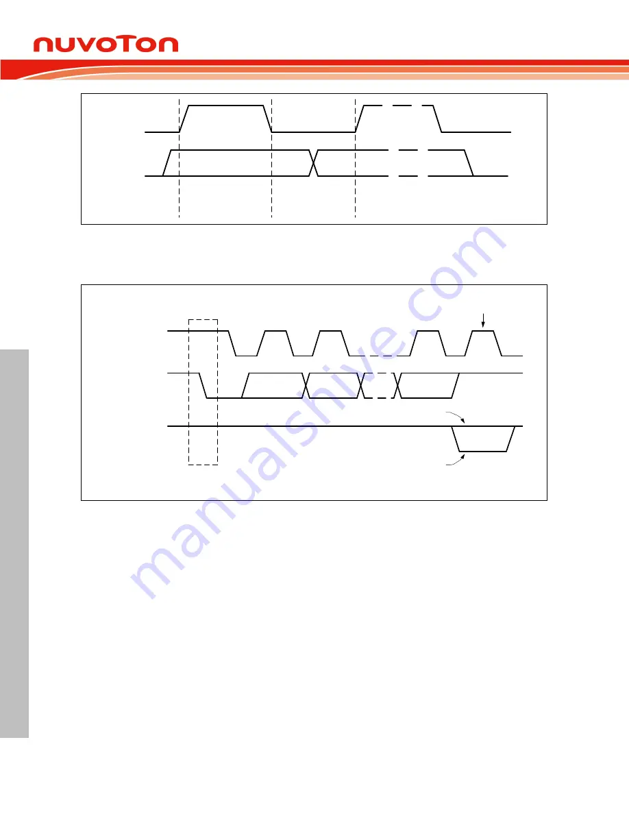
SDA
SCL
Data line stable;
data valid
Change of data
allowed
Figure 6.22-5 Bit Transfer on the I
2
C Bus
If the master received data, does Not Acknowledge (NACK) the slave, the slave releases the SDA line
for the master to generate a STOP or Repeated START signal.
Data Output
by Transmitter
SCL
from Master
START
Condition
Acknowledge
Data Output
by Receiver
S
1
2
8
9
Clock pulse for
acknowledgement
Not acknowledge
Figure 6.22-6 Acknowledge on the I
2
C Bus
6.22.5.5 Clock Baud Rate Bits
For this section, please refer to Figure 6.19-9 basic clock divider counter. The data baud rate of I
2
C is
determines by UI2C_BRGEN register when I
2
C is in Master Mode, and it is not necessary in a Slave
mode. In the Slave mode, I
2
C will automatically synchronize it with any clock frequency from master
I
2
C device. The bits RCLKSEL, SPCLKSEL, PDSCNT, and DSCNT define the baud rate setting:
RCLKSEL (UI2C_BRGEN [0])
to define the input frequency f
REF_CLK
SPCLKSEL (UI2C_BRGEN[3:2])
to define the multiple source of the sample clock f
SAMP_CLK
PDSCNT (UI2C_BRGEN [9:8])
to define the length of a data sample time (division of f
REF_CLK
by 1, 2, 3, or 4)
DSCNT (UI2C_BRGEN [14:10])
to define the number of data sample time per bit time
The standard setting is given by RCLKSEL = 0 (f
REF_CLK
= f
PCLK
), PTCLKSEL = 0 (f
PROT_CLK
= f
REF_CLK
)