


NUC126
Aug. 08, 2018
Page
775
of 943
Rev 1.03
NUC12
6 S
E
RI
E
S
T
E
CH
NI
CA
L R
E
F
E
RE
NCE
MA
NUA
L
6.21 USCI - SPI Mode
6.21.1
Overview
The SPI protocol of USCI controller applies to synchronous serial data communication and allows full
duplex transfer. It supports both master and Slave operation mode with the 4-wire bi-direction
interface. SPI mode of USCI controller performs a serial-to-parallel conversion on data received from a
peripheral device, and a parallel-to-serial conversion on data transmitted to a peripheral device. The
SPI mode is selected by FUNMODE (USPI_CTL[2:0]) = 0x1.
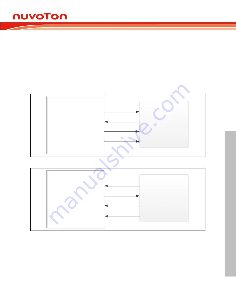
This SPI protocol can operate as master or Slave mode by setting the SLAVE (USPI_PROTCTL[0]) to
communicate with the off-chip SPI Slave or master device. The application block diagrams in master
and Slave mode are shown below.
SPI Slave Device
Master Transmit Data
Master Receive Data
Serial Bus Clock
Slave Select
SPI_MOSI
(USCIx_DAT0)
SPI_MISO
(USCIx_DAT1)
SPI_CLK
(USCIx_CLK)
SPI_SS
(USCIx_CTL)
SPI_MOSI
SPI_MISO
USCI SPI Master
USCI SPI Master
SPI_CLK
SPI_SS
Note:
x = 0, 1, 2
Figure 6.21-1 SPI Master Mode Application Block Diagram
SPI Master Device
Slave Receive Data
Slave Transmit Data
Serial Bus Clock
Slave Select
SPI_MOSI
(USCIx_DAT0)
SPI_MISO
(USCIx_DAT1)
SPI_CLK
(USCIx_CLK)
SPI_SS
(USCIx_CTL)
SPI_MOSI
SPI_MISO
USCI SPI Slave
USCI SPI Slave
SPI_CLK
SPI_SS
Note:
x = 0, 1, 2
Figure 6.21-2 SPI Slave Mode Application Block Diagram
6.21.2
Features
Supports Master or Slave mode operation (the maximum frequency -- Master =
f
PCLK
/ 2,
Slave <
f
PCLK
/ 5)
Configurable bit length of a transfer word from 4 to 16-bit
Supports one transmit buffer and two receive buffers for data payload
Supports MSB first or LSB first transfer sequence
Supports Word Suspend function


