


NUC126
Aug. 08, 2018
Page
599
of 943
Rev 1.03
NUC12
6 S
E
RI
E
S
T
E
CH
NI
CA
L R
E
F
E
RE
NCE
MA
NUA
L
Slave TX Underrun Interrupt
If the TX underflow event occurs, the SLVURIF (SPIx_STATUS[7]) will be set to 1 when SPIx_SS goes
to inactive state. The SPI controller will issue a TX under run interrupt if the SLVURIEN
(SPIx_SSCTL[9]) is set to 1.
Receive Overrun Interrupt
In Slave mode, if the receive FIFO buffer contains 4 unread data, the RXFULL (SPIx_STATUS[9]) will
be set to 1 and the RXOVIF (SPIx_STATUS[11]) will be set to 1 if there is more serial data is received
from SPI bus and follow-up data will be dropped. The SPI controller will issue an interrupt if the
RXOVIEN (SPIx_FIFOCTL[5]) is set to 1.
Receive FIFO Time-out Interrupt
If there is a received data in the FIFO buffer and it is not read by software over 64 SPI peripheral clock
periods in Master mode or over 576 SPI peripheral clock periods in Slave mode, it will send a RX time-
out interrupt to the system if the RX time-out interrupt enable bit, RXTOIEN (SPIx_FIFOCTL[4]), is set
to 1.
Transmit FIFO Interrupt
In FIFO mode, if the valid data count of the transmit FIFO buffer is less than or equal to the setting
value of TXTH (SPIx_FIFOCTL[29:28]), the transmit FIFO interrupt flag TXTHIF (SPIx_STATUS[18])
will be set to 1. The SPI controller will generate a transmit FIFO interrupt to the system if the transmit
FIFO interrupt enable bit, TXTHIEN (SPIx_FIFOCTL[3]), is set to 1.
Receive FIFO Interrupt
In FIFO mode, if the valid data count of the receive FIFO buffer is larger than the setting value of
RXTH (SPIx_FIFOCTL[25:24]), the receive FIFO interrupt flag RXTHIF (SPIx_STATUS[10]) will be set
to 1. The SPI controller will generate a receive FIFO interrupt to the system if the receive FIFO
interrupt enable bit, RXTHIEN (SPIx_FIFOCTL[2]), is set to 1.
6.16.5.9 I
2
S Mode
The SPI0 and SPI1 controllers support I
2
S mode with PCM mode A, PCM mode B, MSB justified and
I
2
S data format. The bit count of an audio channel is determined by WDWIDTH (SPIx_I2SCTL[5:4]).
The transfer sequence is always first from the most significant bit, MSB. Data are read on rising clock
edge and are driven on falling clock edge.
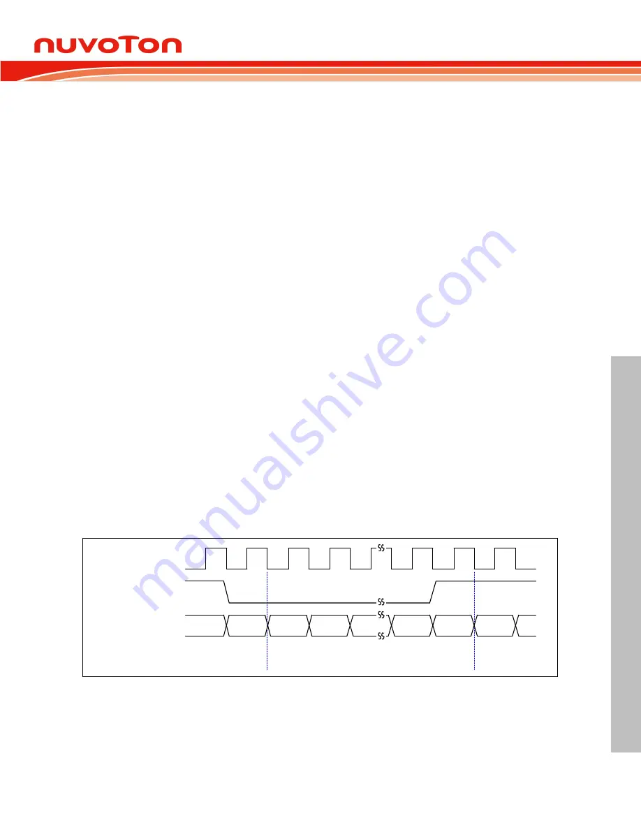
In I
2
S data format, the MSB is sent and latched on the second clock of an audio channel. The
I2Sx_LRCLK signal indicates which audio channel is in transferring.
MSB
word N-1
right channel
word N
left channel
word N+1
right channel
I2Sx_BCLK
I2Sx_LRCLK
I2Sx_DI / I2Sx_DO
LSB
MSB
Figure 6.16-17 I
2
S Data Format Timing Diagram
In MSB justified data format, the MSB is sent and latched on the first clock of an audio channel.


