
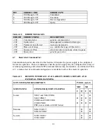


(a)
(b)
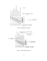
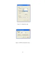
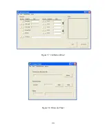
Figure 5.3 Find devices and (b) change device’s GPIB settings
5.3
Command Panel
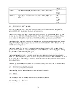
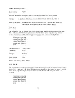
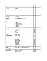
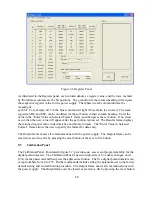
The Command Panel is illustrated in figure 5.5. The Command Panel is organized into three
groups: commands and queries requiring data input, commands with only command syntax, and
commands with only query syntax. The Output frame on the right of the window echoes the
SCPI command used to communicate with the power supply. This feature provides the user with
the proper syntax for each command. The Output frame can be cleared or saved to a file by
pressing the clear button or the save to file button. Commands in gray are not accessible with the
particular configuration.
5.4
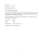
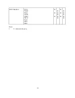
Register Panel
The Register Panel is illustrated in figure 5.6. The Register Panel graphically represents the six
internal registers of the power supply. Register functions, as covered in the previous Chapter, are
briefly summarized below:
1.
Operation register (oper): indicates the power supply’s current operational state. The
register is unlatched and is described in Section 4.3.4.1
2.
Questionable register (ques): indicates the current state of power supply alarms. The
register is unlatched and is described in Section 4.3.4.2.
3.
Status Byte register (STB): indicates communications error messages. The register is
latched and is described in Section 4.5.4.
4.
Service Request Enable register (SRE): a mask register for the STB. The register is
described in Section 4.5.5.
5.
Standard Event Status register (ESR): a latched register which is similar to STB except it
provides more details. The register is described in Section 4.5.2.
6.
Event Status Enable register (ESE): mask register for the ESR. The register is described
in Section 4.5.3.
86
Содержание XR III series
Страница 1: ...OPERATING AND SERVICE MANUAL XR SERIES III DC POWER SUPPLIES...
Страница 2: ......
Страница 3: ...MAGNA POWER ELECTRONICS INC 39 ROYAL ROAD FLEMINGTON NJ 08822 February 20 2012...
Страница 4: ......
Страница 88: ...Figure 4 1 Status Byte Generation Figure 4 2 ESE and ESR Generation 76...
Страница 95: ...IEEE Standard CLS ESR ESE STB SRE IDN SAV RCL RST Notes 1 C command Q query 83...
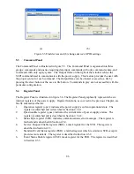
Страница 97: ...Figure 5 1 Configuration setup Figure 5 2 GPIB communications setup 85...
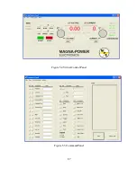
Страница 99: ...Figure 5 4 Virtual Control Panel Figure 5 5 Command Panel 87...
Страница 102: ...Figure 5 7 Calibration Panel Figure 5 8 Firmware Panel 90...
Страница 103: ...Figure 5 9 Modulation Panel 91...
Страница 123: ...Figure B 1 Information Panel Figure B 2 Configure Panel 111...
Страница 124: ...Figure B 3 Reboot in Progress Panel Figure B 4 Web Control Panel 112...


