


3.2.3 Constant Current
To select constant current output, proceed as follows:
With the supply off, set both rotary controls to full counterclockwise. Press the V/I dis key and
advance the voltage and current controls for the desired output current and the desired crossover
voltage. The crossover voltage is the voltage at which the power supply becomes a constant
voltage source.
Connect the load and turn on the power supply. The output current should be close to the current
set point. If a load change causes the voltage limit to be exceeded, the power supply will
automatically crossover to constant voltage output at the preset voltage limit and the output
current will drop proportionately.
3.3
Remote Sensing
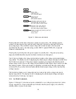
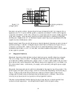
Remote sensing is used to improve the degradation of regulation which will occur at the load
when the voltage drop in the connecting wires is appreciable. This is done by configuring the
power supply for remote sensing as described in Section 3.1.3. Using a pair of #20 AWG wires,
connect terminal 2 of JS2 to the positive terminal of the load and connect terminal 1 of JS2 to the
negative terminal of the load. Figure 3.12 illustrates standard output sensing and remote output
sensing.
Enabling remote sense activates the remote sense lead detector. The remote sense lead detector
checks that the remote sense leads have been connected to the load. With the power supply
configured for remote sensing and upon enabling power output, the sense location is initially set
to local. The sense location is switched to remote upon reaching 7.5% of full scale output
voltage. If the voltage detected is greater than 4.5% of full scale output voltage, the sense
location remains remote; if the output voltage detected is less than 4.5%, then the sense location
will automatically revert back to local.
The remote sense indicator on the front panel will flash when the remote sense configuration has
been selected and the power supply is using local sense. This can occur if the output voltage
never exceeds 7.5% of full scale output voltage or the remote sense lead detector has determined
sense leads are not connected. The remote sense indicator will remain flashing until the remote
sense detector has detected the presence of remote sense voltage within the limits described
above.
34
Содержание XR III series
Страница 1: ...OPERATING AND SERVICE MANUAL XR SERIES III DC POWER SUPPLIES...
Страница 2: ......
Страница 3: ...MAGNA POWER ELECTRONICS INC 39 ROYAL ROAD FLEMINGTON NJ 08822 February 20 2012...
Страница 4: ......
Страница 88: ...Figure 4 1 Status Byte Generation Figure 4 2 ESE and ESR Generation 76...
Страница 95: ...IEEE Standard CLS ESR ESE STB SRE IDN SAV RCL RST Notes 1 C command Q query 83...
Страница 97: ...Figure 5 1 Configuration setup Figure 5 2 GPIB communications setup 85...
Страница 99: ...Figure 5 4 Virtual Control Panel Figure 5 5 Command Panel 87...
Страница 102: ...Figure 5 7 Calibration Panel Figure 5 8 Firmware Panel 90...
Страница 103: ...Figure 5 9 Modulation Panel 91...
Страница 123: ...Figure B 1 Information Panel Figure B 2 Configure Panel 111...
Страница 124: ...Figure B 3 Reboot in Progress Panel Figure B 4 Web Control Panel 112...


