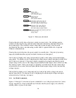


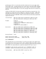


Figure 3.14
Monitoring output (a)
voltage and (b)
current
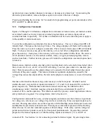
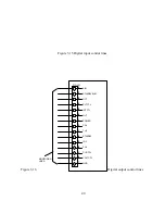
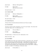
Interlock set requires a either a physical short between terminals 26 and 37 of connector JS1 or
application of a 5.0 V source with the positive connection at terminal 37 of JS1 and the negative
connection at terminal 7 of JS1. One of these two connections must be made to enable operation
of the power supply. If the interlock connection is broken then the loc (interlock) LED lights
and the power supply shuts off. As illustrated, digital control lines may be paralleled with other
supplies to allow simultaneous control.
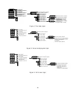
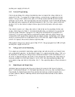
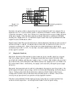
Digital output control lines provide the means to monitor diagnostic functions as well as mode of
operation (voltage or current). All digital output control lines, as illustrated in Figure 3.16, are
connected to connector JS1. Refer to this figure for terminal identification. Each output
monitoring line can drive a 5.0 V, 5.0 mA load. An alarm condition will produce a 5.0 V output
at the respective terminal.
3.7
Diagnostic Functions
Diagnostic functions include thermal overload, interlock, power, standby, phase loss, program
line, over voltage, and over current. All diagnostic indicators have memory retention which
saves the fault condition until the power supply is reset. To clear a fault condition, the user must
press the clear key on the front panel with internal control or by applying 5.0 V to terminal 18 of
JS1 with external control. Alternatively, the supply can be cleared by turning the power supply
off and on.
Diagnostic functions and mode of control are embedded in the supply's closed loop control. The
power supply will operate using voltage control or current control depending on which setting is
lowest. Voltage control and current control also contain a soft start function which causes
voltage and/or current to ramp to the desired set point after power is initiated. The soft start
circuitry is reset upon power-on or operation of any diagnostic function.
Thermal overload indicates that the input power processing devices or output rectifiers have
reached a critical temperature. A resetting thermal breaker will reset upon cooling.
1,2,20
VO2
P/O JS1
5
VO=10V FS
REF GND
24
IO2
IO=10V FS
TO SLAVES
37
INTERLOCK SET
19
STOP
START
17
P/O JS1
26
+5
CLEAR
18
39
Содержание XR III series
Страница 1: ...OPERATING AND SERVICE MANUAL XR SERIES III DC POWER SUPPLIES...
Страница 2: ......
Страница 3: ...MAGNA POWER ELECTRONICS INC 39 ROYAL ROAD FLEMINGTON NJ 08822 February 20 2012...
Страница 4: ......
Страница 88: ...Figure 4 1 Status Byte Generation Figure 4 2 ESE and ESR Generation 76...
Страница 95: ...IEEE Standard CLS ESR ESE STB SRE IDN SAV RCL RST Notes 1 C command Q query 83...
Страница 97: ...Figure 5 1 Configuration setup Figure 5 2 GPIB communications setup 85...
Страница 99: ...Figure 5 4 Virtual Control Panel Figure 5 5 Command Panel 87...
Страница 102: ...Figure 5 7 Calibration Panel Figure 5 8 Firmware Panel 90...
Страница 103: ...Figure 5 9 Modulation Panel 91...
Страница 123: ...Figure B 1 Information Panel Figure B 2 Configure Panel 111...
Страница 124: ...Figure B 3 Reboot in Progress Panel Figure B 4 Web Control Panel 112...


