


Standby indicates that the control circuits are powered, but the supply is disabled through the ac
contactor. This is the power supply's normal off condition. To start the supply, press the start
switch. To place the supply in standby, press the stop switch.
Phase loss indicates a problem with the power mains voltage.
Program line means the voltage set point, current set point, over voltage trip, or over current trip
external input is set beyond the range of control. These lines are constantly monitored and if any
of these references are set above the normal bounds, program line diagnostics will disable the
supply.
Over voltage trip indicates that the supply has exceeded the over voltage trip reference. This
condition causes the supply to shutdown. To clear this condition, the user must press the clear
key on the front panel with internal control or by applying 5.0 V to terminal 18 of JS1 with
external control. To restart the supply, simply press the start switch.
Over current trip indicates that the supply has exceeded the over current trip reference. To clear
this condition, the user must press the clear key on the front panel with internal control or by
applying 5.0 V to terminal 18 of JS1 with external control. To restart the supply, simply press the
start switch.
A secondary over current trip diagnostic provides protection of internal circuitry due to abnormal
line and load conditions or due to failed internal circuitry. This over current trip condition
requires the control power to be recycled by toggling the power switch off and on.
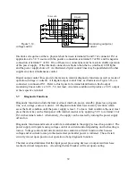
If external interlock is enabled, interlock set requires either a physical short between terminals 26
and 37 of connector JS1 or application of a 5.0 V source with the positive connection at terminal
37 of JS1 and the negative connection at terminal 7 of JS1. If the interlock connection is broken,
then the loc (interlock) LED lights and the power supply shuts down.
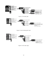
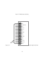
Standby/alm is used with master/slave operation of two or more power supplies. When
interconnected as illustrated in figures 3.17 or 3.18, a standby or alarm condition produced by the
master power supply will turn off the slave power supplies.
Any diagnostic condition causes an alarm condition and the alarm LED to light. This feature can
be used as an external standalone signal to indicate there is a problem.
Other indicators available for monitoring are internal control, external control, voltage mode
control, and current mode control.
3.8
Parallel Operation
Two or more XR Series power supplies can be connected in parallel to obtain a total output
current greater than that available from one power supply. The total output current is the sum of
the output currents of the individual power supplies. Each power supply can be turned on or off
41
Содержание XR III series
Страница 1: ...OPERATING AND SERVICE MANUAL XR SERIES III DC POWER SUPPLIES...
Страница 2: ......
Страница 3: ...MAGNA POWER ELECTRONICS INC 39 ROYAL ROAD FLEMINGTON NJ 08822 February 20 2012...
Страница 4: ......
Страница 88: ...Figure 4 1 Status Byte Generation Figure 4 2 ESE and ESR Generation 76...
Страница 95: ...IEEE Standard CLS ESR ESE STB SRE IDN SAV RCL RST Notes 1 C command Q query 83...
Страница 97: ...Figure 5 1 Configuration setup Figure 5 2 GPIB communications setup 85...
Страница 99: ...Figure 5 4 Virtual Control Panel Figure 5 5 Command Panel 87...
Страница 102: ...Figure 5 7 Calibration Panel Figure 5 8 Firmware Panel 90...
Страница 103: ...Figure 5 9 Modulation Panel 91...
Страница 123: ...Figure B 1 Information Panel Figure B 2 Configure Panel 111...
Страница 124: ...Figure B 3 Reboot in Progress Panel Figure B 4 Web Control Panel 112...


