


unit and the master unit.
3.10
Pulse Loading
The power supply will automatically crossover from constant voltage to constant current
operation, or the reverse, in response to an increase (over the preset limit) in the output current or
voltage, respectively. With the preset limit set to the average output current or voltage, high peak
currents or voltages, as occur in pulse loading, may exceed the preset limit conditions and cause
crossover to occur. To avoid this unwanted crossover, the preset limit must be set for the peak
requirement and not the average.
There are internal capacitors across the output terminals of the power supply. These capacitors
help to supply high-current pulses of short duration during constant voltage operation. Any
capacitance added externally will improve the pulse current capability, but will decrease the
safety provided by the constant current circuit. A high-current pulse may damage load
components before the average output current is large enough to cause the constant current circuit
to operate.
3.11
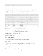
Nomenclature
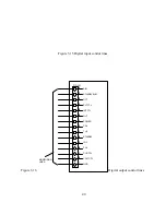
The following defines user connections on the terminal strips and input/output power
connections.
AC INPUT:
A: Phase A input.
B: Phase B input.
C: Phase C input.
GND: Earth ground.
DC OUTPUT:
VO+: Positive output.
VO- : Negative output.
PROGRAMMING INPUTS AND OUTPUTS:
REF GND: Reference ground.
+10V REF: Reference for external analog control.
45
Содержание XR III series
Страница 1: ...OPERATING AND SERVICE MANUAL XR SERIES III DC POWER SUPPLIES...
Страница 2: ......
Страница 3: ...MAGNA POWER ELECTRONICS INC 39 ROYAL ROAD FLEMINGTON NJ 08822 February 20 2012...
Страница 4: ......
Страница 88: ...Figure 4 1 Status Byte Generation Figure 4 2 ESE and ESR Generation 76...
Страница 95: ...IEEE Standard CLS ESR ESE STB SRE IDN SAV RCL RST Notes 1 C command Q query 83...
Страница 97: ...Figure 5 1 Configuration setup Figure 5 2 GPIB communications setup 85...
Страница 99: ...Figure 5 4 Virtual Control Panel Figure 5 5 Command Panel 87...
Страница 102: ...Figure 5 7 Calibration Panel Figure 5 8 Firmware Panel 90...
Страница 103: ...Figure 5 9 Modulation Panel 91...
Страница 123: ...Figure B 1 Information Panel Figure B 2 Configure Panel 111...
Страница 124: ...Figure B 3 Reboot in Progress Panel Figure B 4 Web Control Panel 112...


