


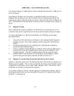


APPENDIX C USB COMMUNICATIONS
The optional Edgeport/1 USB Expansion Module transparently transforms a USB port to a
RS232 COM port.
The Edgeport/1 Windows drivers installs a virtual RS232 COM port in the Device
Manager of the operating system. This in turn will allow communications with the XR
Series power supply in the same manner as a device connected to the RS232 COM port on
a PC. The USB port becomes transparent to the serial device and the software running on
the PC.
C.1
Edgeport/1 Setup
Before installing this optional equipment, the manufacturer recommends that you first
commission the system using the manual controls on the front panel of the power supply.
To connect the Edgeport/1 USB Expansion Module to the XR Series power supply,
proceed as follows:
1.
Connect the USB cable between a USB port on the computer and the Edgeport/1
Expansion module. This cable is supplied with the Edgeport/1 USB Expansion
Module.
2.
If required, install the drivers for the Edgeport/1 USB Expansion Module as
described in the Installation Guide.
3.
Connect a standard, straight-through, 9-conductor, serial extension cable between
connector JS3 on the power supply and the serial port on the Edgeport/1 USB
Expansion Module. This cable is supplied with the XR Series power supply.
4.
Establish RS232 communications by configuring the power supply for remote
operation using the front panel commands described in Section 3.1.3.
C.2
Edgeport/1 Communications using the Remote Interface Software
Chapter 5.0 describes application of the Remote Interface Software which is shipped with
XR Series power supplies. This software provides the user with a quick method to operate
a Magna-Power Electronics’ power supply under computer control. The software can be
configured for a number of communication interfaces.
To use Remote Interface Software with the Edgeport/1 USB Expansion Module, perform
the setup described in previous section and refer to Section 5.1 to configure the software
for RS232 communications.
113
Содержание XR III series
Страница 1: ...OPERATING AND SERVICE MANUAL XR SERIES III DC POWER SUPPLIES...
Страница 2: ......
Страница 3: ...MAGNA POWER ELECTRONICS INC 39 ROYAL ROAD FLEMINGTON NJ 08822 February 20 2012...
Страница 4: ......
Страница 88: ...Figure 4 1 Status Byte Generation Figure 4 2 ESE and ESR Generation 76...
Страница 95: ...IEEE Standard CLS ESR ESE STB SRE IDN SAV RCL RST Notes 1 C command Q query 83...
Страница 97: ...Figure 5 1 Configuration setup Figure 5 2 GPIB communications setup 85...
Страница 99: ...Figure 5 4 Virtual Control Panel Figure 5 5 Command Panel 87...
Страница 102: ...Figure 5 7 Calibration Panel Figure 5 8 Firmware Panel 90...
Страница 103: ...Figure 5 9 Modulation Panel 91...
Страница 123: ...Figure B 1 Information Panel Figure B 2 Configure Panel 111...
Страница 124: ...Figure B 3 Reboot in Progress Panel Figure B 4 Web Control Panel 112...


