


3.
Verify the availability of the RS232 port selected.
4.
Turn on the power switch of the XR Series power supply and turn on the IBM PC or
compatible computer.
5.
Start the HyperTerminal test software and set the COM port to the one connected to the
XR Series power supply. Configure the terminal for 19200, N, 8, 1. Set the terminal to
echo typed characters locally and “append line feeds to incoming line ends.” (The echo
feature is not functional with Windows 98.)
6.
Type the query command “*IDN?” in the output data window and press enter. The text
should be entered inside the quotation marks.
7.
As illustrated in figure 4.1, the returned data will display the following:
“Magna-Power Electronics, Inc., XR16-375, SN: 1162-0361” where the model and serial
number may be different depending on the unit being tested.
8.
Verify that the model number in the *IDN? response corresponds to the power supply
under test. If this is not the case, configure the supply using the steps outlined in Section
4.3.9.1 CAL:IDN.
9.
With the output terminals of the power supply open, enter the command VOLT xx where
xx is 50% of rated voltage and press enter. Press the display key on the front panel of the
power supply and verify that the set point is 50% of rated voltage.
10.
Enter the command OUTP:START and press enter. The power supply’s contactor should
close with an audible click and the front panel indicators and meters should indicate
power flow. Verify that the power supply’s output voltage is equal to the VOLT setting
set in the previous command.
11.
Enter the command MEAS:VOLT? and press enter. Verify the output voltage
corresponds the voltmeter on the front panel of the power supply.
12.
Enter the command OUTP:STOP and press enter. The power supply’s contactor should
open with an audible click and the front panel indicators and meters should indicate
operation in a standby state.
4.3
SCPI Subsystem Commands
The SCPI command set is broken down into sub-systems as described in the following Sections of
this chapter. The syntax for data formats of the SCPI command set is defined in Section 4.3.15.
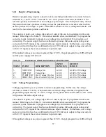
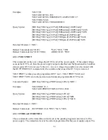
4.3.1 Source Subsystem
This subsystem programs the voltage set point, current set point, over voltage trip, over current
trip, and period of the power supply.
49
Содержание XR III series
Страница 1: ...OPERATING AND SERVICE MANUAL XR SERIES III DC POWER SUPPLIES...
Страница 2: ......
Страница 3: ...MAGNA POWER ELECTRONICS INC 39 ROYAL ROAD FLEMINGTON NJ 08822 February 20 2012...
Страница 4: ......
Страница 88: ...Figure 4 1 Status Byte Generation Figure 4 2 ESE and ESR Generation 76...
Страница 95: ...IEEE Standard CLS ESR ESE STB SRE IDN SAV RCL RST Notes 1 C command Q query 83...
Страница 97: ...Figure 5 1 Configuration setup Figure 5 2 GPIB communications setup 85...
Страница 99: ...Figure 5 4 Virtual Control Panel Figure 5 5 Command Panel 87...
Страница 102: ...Figure 5 7 Calibration Panel Figure 5 8 Firmware Panel 90...
Страница 103: ...Figure 5 9 Modulation Panel 91...
Страница 123: ...Figure B 1 Information Panel Figure B 2 Configure Panel 111...
Страница 124: ...Figure B 3 Reboot in Progress Panel Figure B 4 Web Control Panel 112...


