


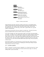


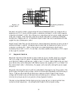


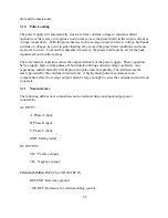

Figure 3.10 Set external interlock
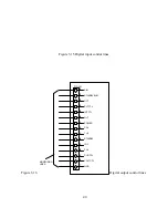
3.1.4 Calibration Commands
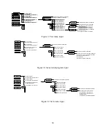
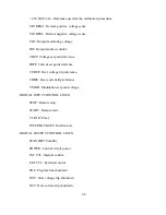
Figure 3.11 describes the calibration commands. Calibration commands allow calibration of five
digital potentiometers, display of the firmware and hardware revisions, and reset the digital
potentiometers to the factory calibration settings. All of these commands can be made when the
power supply is in either the standby or power mode state.
To enter the calibration commands, first press the menu key. The over voltage trip LED will
initially flash. Then press the item key 3 times. The voltage display will flash CAL
(calibration). Press enter for 10 seconds or press clear to exit the calibration command menu.
Upon entering the calibration commands, the output voltage will be displayed in the voltage
display, the potentiometer setting, 0 to 255, will be displayed in the right three digits of the
current display, and P and 1 will alternately flash in the left digit of the current display.
Potentiometer 1 adjusts the gain of the voltage feedback amplifier, potentiometer 2 adjusts the
input offset voltage of the voltage feedback amplifier, potentiometer 3 adjusts the gain of the
current feedback amplifier, potentiometer 4 adjusts the input offset voltage of the current
feedback amplifier, and potentiometer 5 adjusts the gain of the reference which is used for the
digital to analog and analog to digital converters.
Pressing the item key advances control to potentiometer 2. The left digit of the current display
will alternately flash P and 2, the output voltage will be displayed in the voltage display, and the
potentiometer setting, 0 to 255, will be displayed in the right three digits of the current display.
Pressing the item key again will advance the control to potentiometer 3. Now the output current
will be displayed in the current display, the potentiometer setting, 0 to 255, will be displayed in
the right three digits of the voltage display, and the left digit of the voltage display will
alternately flash P and 3.
31
Содержание XR III series
Страница 1: ...OPERATING AND SERVICE MANUAL XR SERIES III DC POWER SUPPLIES...
Страница 2: ......
Страница 3: ...MAGNA POWER ELECTRONICS INC 39 ROYAL ROAD FLEMINGTON NJ 08822 February 20 2012...
Страница 4: ......
Страница 88: ...Figure 4 1 Status Byte Generation Figure 4 2 ESE and ESR Generation 76...
Страница 95: ...IEEE Standard CLS ESR ESE STB SRE IDN SAV RCL RST Notes 1 C command Q query 83...
Страница 97: ...Figure 5 1 Configuration setup Figure 5 2 GPIB communications setup 85...
Страница 99: ...Figure 5 4 Virtual Control Panel Figure 5 5 Command Panel 87...
Страница 102: ...Figure 5 7 Calibration Panel Figure 5 8 Firmware Panel 90...
Страница 103: ...Figure 5 9 Modulation Panel 91...
Страница 123: ...Figure B 1 Information Panel Figure B 2 Configure Panel 111...
Страница 124: ...Figure B 3 Reboot in Progress Panel Figure B 4 Web Control Panel 112...


