


7.0 MAINTENANCE AND TROUBLE SHOOTING
7.1
General
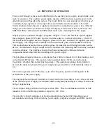
The XR Series power supplies consist of a multistage power processing system. Because of its
complexity, it is highly recommended that all repairs be performed by the factory or qualified
power supply technician. Before attempting maintenance or repair, the technician should be
familiar with the components of the systems and the theory of operation. Some basic test
equipment is also necessary: source of ac power, means of loading the power supply, dc voltmeter
with accuracy and resolution better than the unit specifications, and an oscilloscope. The chart in
Section 7.2 should aid in finding operational problems.
Caution: When servicing the power supply, dangerous voltage levels exist.
All ac and dc capacitors should be discharged. Be especially careful of
person and equipment when measuring primary circuitry since this is at line
potential.
7.2
Trouble Shooting Guide
1.
Fuse F1, F2, or F3 blows when the power supply is turned on. Power supply has a short
on the primary side.
a.
Check diode bridge DB1.
b.
Check for failed power semiconductor on the Chopper Module.
c.
Check for isolation to ground on the input side of the power supply.
2.
Over current trips and power supply cannot be reset. An auxiliary over current detector
limits input dc link current. Exceeding safe levels will cause an over current diagnostic
condition that cannot be reset.
a.
Restart the supply. Transient voltages on the input voltage could have caused the
problem.
b.
Check diodes D1 through D4 on the secondary side of transformer T1.
c.
Check for a shorted winding on transformer T1.
d.
Check for failed IGBT’s in the chopper and current fed inverter circuitry.
3.
Unit goes to high output immediately after starting.
a.
Check for loose connectors internal to the power supply.
4.
High ripple voltage.
a.
Check the mains voltage for balance and magnitude.
95
Содержание XR III series
Страница 1: ...OPERATING AND SERVICE MANUAL XR SERIES III DC POWER SUPPLIES...
Страница 2: ......
Страница 3: ...MAGNA POWER ELECTRONICS INC 39 ROYAL ROAD FLEMINGTON NJ 08822 February 20 2012...
Страница 4: ......
Страница 88: ...Figure 4 1 Status Byte Generation Figure 4 2 ESE and ESR Generation 76...
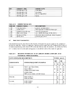
Страница 95: ...IEEE Standard CLS ESR ESE STB SRE IDN SAV RCL RST Notes 1 C command Q query 83...
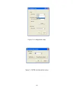
Страница 97: ...Figure 5 1 Configuration setup Figure 5 2 GPIB communications setup 85...
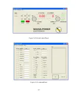
Страница 99: ...Figure 5 4 Virtual Control Panel Figure 5 5 Command Panel 87...
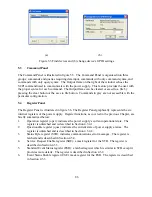
Страница 102: ...Figure 5 7 Calibration Panel Figure 5 8 Firmware Panel 90...
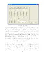
Страница 103: ...Figure 5 9 Modulation Panel 91...
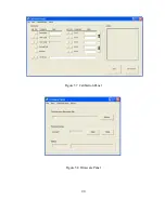
Страница 123: ...Figure B 1 Information Panel Figure B 2 Configure Panel 111...
Страница 124: ...Figure B 3 Reboot in Progress Panel Figure B 4 Web Control Panel 112...


