


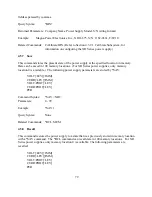


(default) 0 disabled
disabled
1 Vom=Vo×Mod
Vom=Vo+Mod
2 Iom=Io×Mod
Iom=Io+Mod
Notes:
1) Vom is the adjusted output voltage as a function of the modulation operator
2) Iom is the adjusted output current as a function of the modulation operator
3) Vo is the output voltage as a function of input set point voltage
4) Io is the output current as a function of set point current
5) Mod is a value derived from a lookup table as determined by an analog interface
signal,VMOD. Mod is made continuous using a piecewise linear approximation algorithm. In
type 0 modulation, Mod is unitless. In type 1 modulation, Mod represents either a voltage or
current for control inputs 1 or 2, respectively.
Command Syntax:
MODulation:TYPE:SELect <NR1>[,<NR1>]
Examples:
MOD:TYPE:SEL 1,0
MOD:TYPE:SEL 2,1
MODulation:TYPE:SELect 0
Query Syntax:
MODulation:TYPE:SELect?
Returned Parameters: <NR1>,<NR1>
Related Commands: None
4.3.14.2 MOD:TABL
This command programs the user defined modulation table described in Section 4.3.14.1. The
feature allows the user to program nonlinear output voltage and current profiles to fit their
application needs, such as source emulation or output adjustments with respect to an external
sensor.
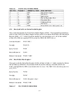
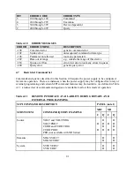
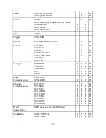
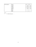
The lookup table contains 4 columns and up to 50 rows; it stores an output profile as a function of
the analog input voltage applied to terminal 25 of JS1, VMOD. As shown in Table 4.4, the first
column stores the table row and the second column sets an analog input VMOD. The third
column store the Mod value associated with VMOD for that table row.
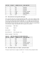
The fourth column of the lookup table, Loc, defines whether the table is stored in an active or
temporary location. Certain applications may need to transition between different tables while
the power supply is still running. For example, emulation of solar panel’s voltage/current
characteristics requires continuous external data acquisition along with quick and smooth table
loading . The modulation subsystem provides two storage locations, Loc 0 or 1, to help improve
table loading performance. With Loc set to 0, data will be stored to the Active Table, the table
71
Содержание XR III series
Страница 1: ...OPERATING AND SERVICE MANUAL XR SERIES III DC POWER SUPPLIES...
Страница 2: ......
Страница 3: ...MAGNA POWER ELECTRONICS INC 39 ROYAL ROAD FLEMINGTON NJ 08822 February 20 2012...
Страница 4: ......
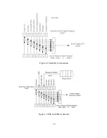
Страница 88: ...Figure 4 1 Status Byte Generation Figure 4 2 ESE and ESR Generation 76...
Страница 95: ...IEEE Standard CLS ESR ESE STB SRE IDN SAV RCL RST Notes 1 C command Q query 83...
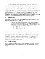
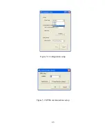
Страница 97: ...Figure 5 1 Configuration setup Figure 5 2 GPIB communications setup 85...
Страница 99: ...Figure 5 4 Virtual Control Panel Figure 5 5 Command Panel 87...
Страница 102: ...Figure 5 7 Calibration Panel Figure 5 8 Firmware Panel 90...
Страница 103: ...Figure 5 9 Modulation Panel 91...
Страница 123: ...Figure B 1 Information Panel Figure B 2 Configure Panel 111...
Страница 124: ...Figure B 3 Reboot in Progress Panel Figure B 4 Web Control Panel 112...


