
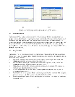
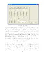


Figure 5.6 Register Panel
As illustrated in the Register panel, each column denotes a register value, and the rows, marked
by the leftmost column, are the bit positions. The get button at the column heading will acquire
the respective register value for the power supply. The labels in each column indicate the
meaning of
each bit. For example, bit 5 in the Ques column will light if fuse alarm is activated. The mask
registers, SRE and ESE, can be modified via the set button in their column heading. Enter the
value in the “Enter Value in Selected Format” frame, and then press the set button. If no errors
occur, then the new value will appear after the get button is pressed. The Results frame displays
the returned register value in decimal, hex and binary formats. The “Enter Value in Selected
Format” frame allows the user to specify the format for data entry.
The Output frame shows all communications with the power supply. The Output frame can be
cleared or saved to a file by pressing the clear button or the save to file button.
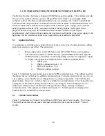
5.5
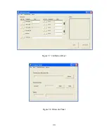
Calibration Panel
The Calibration Panel, illustrated in figure 5.7, provides easy access and programmability for the
digital potentiometers. The Calibration Panel is password protected. To enable changes, enter
1234 for the password and then press the adjacent set button. The five digital potentiometers can
accept numbers from 0 to 255. Further commands include setting the potentiometer to the factory
default setting and end calibration procedure. The Output frame shows all communications with
the power supply. The Output frame can be cleared or saved to a file by pressing the clear button
88
Содержание XR III series
Страница 1: ...OPERATING AND SERVICE MANUAL XR SERIES III DC POWER SUPPLIES...
Страница 2: ......
Страница 3: ...MAGNA POWER ELECTRONICS INC 39 ROYAL ROAD FLEMINGTON NJ 08822 February 20 2012...
Страница 4: ......
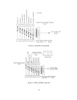
Страница 88: ...Figure 4 1 Status Byte Generation Figure 4 2 ESE and ESR Generation 76...
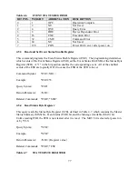
Страница 95: ...IEEE Standard CLS ESR ESE STB SRE IDN SAV RCL RST Notes 1 C command Q query 83...
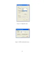
Страница 97: ...Figure 5 1 Configuration setup Figure 5 2 GPIB communications setup 85...
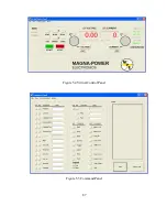
Страница 99: ...Figure 5 4 Virtual Control Panel Figure 5 5 Command Panel 87...
Страница 102: ...Figure 5 7 Calibration Panel Figure 5 8 Firmware Panel 90...
Страница 103: ...Figure 5 9 Modulation Panel 91...
Страница 123: ...Figure B 1 Information Panel Figure B 2 Configure Panel 111...
Страница 124: ...Figure B 3 Reboot in Progress Panel Figure B 4 Web Control Panel 112...


