


4.0 PROGRAMMING WITH SCPI COMMANDS
4.1
Command Features
XR Series power supplies provide RS232 communications as a standard feature and IEEE-488 or
Ethernet communications as an optional feature. A second UART port, a factory installed option,
is enabled after power on by recognizing which port is receiving communications. Once a
particular port has been activated, the other UART port cannot be recognized unless there has
been a period of inactivity for 5 minutes. After this period, a new UART port can be recognized
by sending communications.
In addition to RS232, IEEE-488, or Ethernet communications, other communications options are
possible using external RS232 converter modules. These modules transparently converts data
between the RS232 port and the one tied to communications system. Refer to the Appendixes for
details on the optional communications ports and the external converter modules.
An IVI-COM Driver is included with the installation CD and is available for download from the
Magna-Power Electronics’ web page. The driver allows the power supply to communicate
through many different programming languages. The driver handles the low-level bus protocols
simplifying automation development. It supports TCP/IP, GPIB, and RS232 using standard VISA
resource descriptors. For additional documentation and details on using the IVI-COM driver, see
the driver's included help file (MPEIVI.chm).
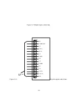
The RS232 port, connector JS3, located on the rear panel, allows all of the front panel functions
plus some additional commands to be implemented using SCPI commands. To establish RS232
communications, configure the power supply for remote operation using the front panel
commands described in Sections 3.1.3, set the RS232 interface to the specifications detailed in
Section 1.5, and connect a 9-conductor straight through, D-subminiature cable between the
computer interface and connector JS3.
RS232 communications to the XR Series power supply can be made using a Terminal program or
with the Remote Interface Software supplied with the power supply. The Remote Interface
Software, covered in Section 5.0, contains command output frames to display the SCPI command
being written to obtain the desired result. This feature provides feedback to the user to help
program with SCPI commands.
4.2
Electrical Testing Using RS232 Communications
XR Series power supplies can be tested using any Terminal program: one is included with
Microsoft Windows (tm) called HyperTerminal. The following outlines the procedure.
1.
Configure the power supply for remote operation using the front panel commands
described in Section 3.1.3.
2.
Connect a 9-conductor straight through, D-subminiature cable between the computer
interface and connector JS3 at the rear of the power supply.
48
Содержание XR III series
Страница 1: ...OPERATING AND SERVICE MANUAL XR SERIES III DC POWER SUPPLIES...
Страница 2: ......
Страница 3: ...MAGNA POWER ELECTRONICS INC 39 ROYAL ROAD FLEMINGTON NJ 08822 February 20 2012...
Страница 4: ......
Страница 88: ...Figure 4 1 Status Byte Generation Figure 4 2 ESE and ESR Generation 76...
Страница 95: ...IEEE Standard CLS ESR ESE STB SRE IDN SAV RCL RST Notes 1 C command Q query 83...
Страница 97: ...Figure 5 1 Configuration setup Figure 5 2 GPIB communications setup 85...
Страница 99: ...Figure 5 4 Virtual Control Panel Figure 5 5 Command Panel 87...
Страница 102: ...Figure 5 7 Calibration Panel Figure 5 8 Firmware Panel 90...
Страница 103: ...Figure 5 9 Modulation Panel 91...
Страница 123: ...Figure B 1 Information Panel Figure B 2 Configure Panel 111...
Страница 124: ...Figure B 3 Reboot in Progress Panel Figure B 4 Web Control Panel 112...


