


turn the power switch on.
Press the start switch and advance the voltage control one turn clockwise. Increase the current
set point to maximum and then to minimum. The power and current control indicators should
light. Dc current should increase smoothly from minimum to maximum to minimum as
indicated on the meter. Return the current control full counterclockwise. Press the stop switch.
To check over current trip, press the menu key and the item key one time. This places the power
supply in data entry mode to set over current trip. Using the up/down arrow keys, enter an over
current trip set point at half the rating of the power supply. Once the over current trip set point
has been entered, press the enter key to save the information.
Press the start switch and slowly increase the current set point. Over current trip should operate
at the over current trip set point. The over current trip (OCT) indicator should turn on, the power
and current control indicators should turn off, and the supply should shut down. Press the clear
key. Now set the over current trip set point to maximum which is 110% the full scale rating of
the power supply. Again start the supply and observe that the power supply operates normally.
If any of these events do not occur, the supply is defective and should not be operated.
Depending on the circumstances, either warranty service or trouble shooting, as described in
Section 7.2, is required.
2.6.2.2 XRC Series Models
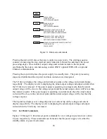
The electrical check for XRC Series models require use of the Remote Interface Software
described in Section 5.0. With the software installed and the power supply connected to the
desired communications interface, select XR Version in the Configuration Setup Panel. Select
the Virtual Control Panel in the View Menu to display the XR Version front panel. Follow the
procedure outlined in Section 2.6.2.1 using the Virtual Control Panel.
22
Содержание XR III series
Страница 1: ...OPERATING AND SERVICE MANUAL XR SERIES III DC POWER SUPPLIES...
Страница 2: ......
Страница 3: ...MAGNA POWER ELECTRONICS INC 39 ROYAL ROAD FLEMINGTON NJ 08822 February 20 2012...
Страница 4: ......
Страница 88: ...Figure 4 1 Status Byte Generation Figure 4 2 ESE and ESR Generation 76...
Страница 95: ...IEEE Standard CLS ESR ESE STB SRE IDN SAV RCL RST Notes 1 C command Q query 83...
Страница 97: ...Figure 5 1 Configuration setup Figure 5 2 GPIB communications setup 85...
Страница 99: ...Figure 5 4 Virtual Control Panel Figure 5 5 Command Panel 87...
Страница 102: ...Figure 5 7 Calibration Panel Figure 5 8 Firmware Panel 90...
Страница 103: ...Figure 5 9 Modulation Panel 91...
Страница 123: ...Figure B 1 Information Panel Figure B 2 Configure Panel 111...
Страница 124: ...Figure B 3 Reboot in Progress Panel Figure B 4 Web Control Panel 112...


