
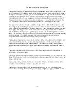


8.6
High-Slew Rate Option
The standard output stage of XR Series power supplies has been designed to provide the
lowest possible output ripple voltage within the constraints of available components, size,
and cost. Part of the output stage consists of a bank of aluminum electrolytic capacitors
which has the desired electrical properties to provide this function. These components
require bleed resistors to discharge any voltage when the power supply has no load and is
disabled. While the presence of these components and the resulting performance are
normally industry accepted, there are applications where lower output capacitance and
lower loss bleed resistors are extremely desirable and higher ripple voltage is acceptable.
To meet this need, a high-slew rate option is available which has an output stage consisting
of low capacitance film and aluminum electrolytic capacitors and lower loss bleed
resistors. Applications for the high-slew rate option include battery charging, photovoltaic
emulation, power waveform generation, and medium speed power pulsing. These
applications all benefit from higher bandwidth and in many case, can tolerate increased
ripple voltage.
The high slew rate option in XR Series power supplies solves several problems inherent in
switching power supply design. Rapid voltage transitions require internal electronics to
supply the energy to charge and discharge output capacitors. Peak currents internal to the
power supply define slew rate; utilizing less capacitance enables voltage transitions in
shorter time periods. Additionally, less capacitance reduces requirements for discharge
demands during open circuit conditions.
For battery charger applications, output capacitance and internal bleed resistors present
itself as a load to the connecting batteries. One common practice is to use a series diode to
block reverse current flow with the sacrifice of increased cost and lower efficiency. The
high slew rate option, with its lower output capacitance and lower loss bleed resistors,
enables direct connection to batteries without series blocking diodes.
For photovoltaic emulation applications, higher bandwidth and lower output capacitance
enable improved performance with higher speed, maximum power tracker algorithms.
Maximum power tracker circuitry deviates the operating point of photovoltaic arrays to
determine maximum power output. Slow responding emulation sources can present a
problem when the speed of the algorithm exceeds that of the source. Furthermore, with
lower output capacitance, changes in the operating point and transients, caused by shorting
the solar inverter input, produce lower unwanted input currents.
The high-slew rate option enables a XR Series power supply to operate as a low frequency,
power pulse generator. With the special capacitors selected for this option, it is possible to
superimpose waveforms or produce a medium speed pulse on top of the dc output and
expect normal capacitor life. It is important to note that the power supply output is single
quadrant; that is, the output voltage or current cannot reverse.
104
Содержание XR III series
Страница 1: ...OPERATING AND SERVICE MANUAL XR SERIES III DC POWER SUPPLIES...
Страница 2: ......
Страница 3: ...MAGNA POWER ELECTRONICS INC 39 ROYAL ROAD FLEMINGTON NJ 08822 February 20 2012...
Страница 4: ......
Страница 88: ...Figure 4 1 Status Byte Generation Figure 4 2 ESE and ESR Generation 76...
Страница 95: ...IEEE Standard CLS ESR ESE STB SRE IDN SAV RCL RST Notes 1 C command Q query 83...
Страница 97: ...Figure 5 1 Configuration setup Figure 5 2 GPIB communications setup 85...
Страница 99: ...Figure 5 4 Virtual Control Panel Figure 5 5 Command Panel 87...
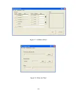
Страница 102: ...Figure 5 7 Calibration Panel Figure 5 8 Firmware Panel 90...
Страница 103: ...Figure 5 9 Modulation Panel 91...
Страница 123: ...Figure B 1 Information Panel Figure B 2 Configure Panel 111...
Страница 124: ...Figure B 3 Reboot in Progress Panel Figure B 4 Web Control Panel 112...


