
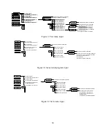


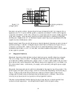


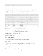
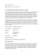

Figure 3.17 Master/slave parallel connection
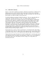
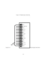
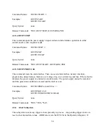
Figure 3.18 Master/slave series connection
The slave power supply must be configured for external program input. The master unit can
configured for rotary, external program, or remote input. Configuration commands are discussed
in Section 3.1.3.
To add a second slave unit, connect the output terminals of the second slave in parallel with the
other two power supplies. Furthermore, connect a second control cable between the second slave
unit and the master unit.
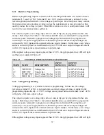
3.9
Series Operation
Two or more power supplies can be connected in series to obtain a total output voltage greater
than that available from one power supply. The total output voltage is the sum of the output
voltage of the individual power supplies. Each power supply can be turned on or off separately.
P/O JS1
22
2
VO+
VO-
LOAD
SLAVE
CURRENT
MODE CONTROL
MASTER
REF GND
VO-
VO+
IO2
2
24
P/O JS1
TO SECOND
SLAVE
REF GND
IREF EXT
VREF EXT
REF GND
SLAVE
TO SECOND
P/O JS1
5
2
VO2
VO+
VO-
REF GND
MASTER
MODE CONTROL
VOLTAGE
SLAVE
LOAD
VO-
VO+
2
3
P/O JS1
12
STANDBY/ALM
POWER
8
START
STOP
19
17
21
REF
TVREF EXT
4
23
TIREF EXT
3
VREF EXT
POWER
STANDBY/ALM
8
12
17
19
STOP
START
IREF EXT
22
TIREF EXT
23
4
TVREF EXT
21
REF
VO2
5
IO2
24
43
Содержание XR III series
Страница 1: ...OPERATING AND SERVICE MANUAL XR SERIES III DC POWER SUPPLIES...
Страница 2: ......
Страница 3: ...MAGNA POWER ELECTRONICS INC 39 ROYAL ROAD FLEMINGTON NJ 08822 February 20 2012...
Страница 4: ......
Страница 88: ...Figure 4 1 Status Byte Generation Figure 4 2 ESE and ESR Generation 76...
Страница 95: ...IEEE Standard CLS ESR ESE STB SRE IDN SAV RCL RST Notes 1 C command Q query 83...
Страница 97: ...Figure 5 1 Configuration setup Figure 5 2 GPIB communications setup 85...
Страница 99: ...Figure 5 4 Virtual Control Panel Figure 5 5 Command Panel 87...
Страница 102: ...Figure 5 7 Calibration Panel Figure 5 8 Firmware Panel 90...
Страница 103: ...Figure 5 9 Modulation Panel 91...
Страница 123: ...Figure B 1 Information Panel Figure B 2 Configure Panel 111...
Страница 124: ...Figure B 3 Reboot in Progress Panel Figure B 4 Web Control Panel 112...


