


or the save to file button.
Voltage Scale and Current Scale are not available to the user. These are factory specific
commands that require an alternate password to access.
5.6
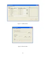
Firmware Panel
The Firmware Panel is illustrated in figure 5.8. The Firmware Panel enables the program stored
internal to the power supply to be upgraded. The factory recommends that firmware upgrades be
performed only if there is an operational problem with the power supply.
The following steps list the procedure for upgrading the firmware:
1.
Turn the power supply off.
2.
Connect a RS232 cable between a serial port on a computer and connector JS3 on the
power supply.
3.
Press the select button and choose the file to be loaded.
4.
Press the start button. The Status frame will display “Initiating.”
5.
Turn on the power supply. If the supply is not turned on within 10 seconds, “Time Out”
will be displayed in the Status frame indicating communications is lost.
During the process of upgrading the firmware, the front panel of the power supply will remain
blank. After communications is established, the Status frame will initially display “Erasing” and
the Current Address frame will display the address in memory being erased. After the entire
memory is erased, the Status frame will display “Loading ” and the Current Address frame will
display the address in memory being loaded. The Status frame will display “Finished” and the
front panel display will return to normal after the memory is reprogrammed..
Pressing the stop button will terminate execution at any time.
5.7
Modulation Panel
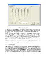
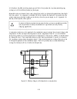
The Modulation Panel is illustrated in figure 5.9. The Modulation Panel enables a user to set and
view the modulation settings as described in Section 4.3.14. The modulation settings consist of
control input, modulation type (multiplication or addition), table row, modulation voltage input,
and modulation factor. The Modulation Panel provides the form to program a linear or piece-
wise linear lookup table for the selected modulation type. The lookup table can have a maximum
of 50 data points. The modulation voltage input, VMOD, must be entered in ascending order.
For lookup tables with less than 50 data points, VMOD must be terminated with a Mod value of
9999. Any data entered for modulation factor on the terminating row is ignored. The Output
frame on the right of the window displays all of the communications with the power supply. The
Output frame can be cleared or saved to a file by pressing the clear button or the save to file
button.
89
Содержание XR III series
Страница 1: ...OPERATING AND SERVICE MANUAL XR SERIES III DC POWER SUPPLIES...
Страница 2: ......
Страница 3: ...MAGNA POWER ELECTRONICS INC 39 ROYAL ROAD FLEMINGTON NJ 08822 February 20 2012...
Страница 4: ......
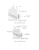
Страница 88: ...Figure 4 1 Status Byte Generation Figure 4 2 ESE and ESR Generation 76...
Страница 95: ...IEEE Standard CLS ESR ESE STB SRE IDN SAV RCL RST Notes 1 C command Q query 83...
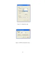
Страница 97: ...Figure 5 1 Configuration setup Figure 5 2 GPIB communications setup 85...
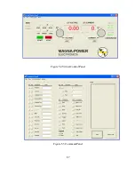
Страница 99: ...Figure 5 4 Virtual Control Panel Figure 5 5 Command Panel 87...
Страница 102: ...Figure 5 7 Calibration Panel Figure 5 8 Firmware Panel 90...
Страница 103: ...Figure 5 9 Modulation Panel 91...
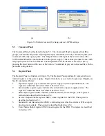
Страница 123: ...Figure B 1 Information Panel Figure B 2 Configure Panel 111...
Страница 124: ...Figure B 3 Reboot in Progress Panel Figure B 4 Web Control Panel 112...


