


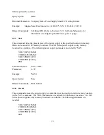


locations are available for programming.
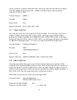
The query command, MEM?, returns the current memory location.
Command Syntax:
[RECall]:MEMory <NR1>
Examples:
REC:MEM 10
MEM 99
Query Syntax:
RECall:MEMory?
Returned Parameters: <NR1>
Related Commands: *RCL, *SAV
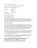
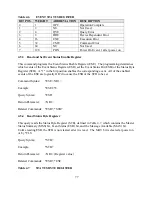
4.3.14 Modulation Subsystem
The Modulation Subsystem adjusts the output voltage or current according to the voltage
measured on the external analog input, pin 25 of JS1, named VMOD. This signal has an allowed
input range 0-10 V. Modulation requires the power supply to be configured for remote mode.
Rotary mode control or external program mode control cannot be used with this command
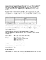
4.3.14.1 MOD:TYPE:SEL
This command is composed of two comma separated, modulation parameters. The first
parameter, control input, defines whether the modulation table adjusts output voltage or output
current. When the control input is set to 1, VMOD selects the modulation table to adjust output
voltage. When control input is set to 2, VMOD selects the modulation table adjust to output
current. Setting the control input to the default value of 0, disables the modulation function.
Information on programming the lookup table is provided in Section 4.3.14.2.
The second command parameter, type, defines the expression for modulating output voltage or
current. With type set to 0, table data points are used in a multiplying expression. With type set
to 1, table data points are used in an addition expression. The alternatives for modulation
expressions are illustrated in Table 4.3.
The choice of using type 0 or type 1 modulation depends on the application. Only one set point
can be modulated at any given time. The query command returns two comma separated
parameters, the control input followed by the algorithm.
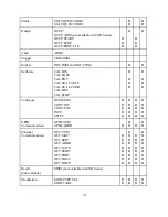
Table 4.3
MODULATION FUNCTION SUBSYSTEM PARAMETERS
Control
Input
Type
0
1
70
Содержание XR III series
Страница 1: ...OPERATING AND SERVICE MANUAL XR SERIES III DC POWER SUPPLIES...
Страница 2: ......
Страница 3: ...MAGNA POWER ELECTRONICS INC 39 ROYAL ROAD FLEMINGTON NJ 08822 February 20 2012...
Страница 4: ......
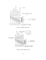
Страница 88: ...Figure 4 1 Status Byte Generation Figure 4 2 ESE and ESR Generation 76...
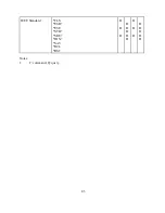
Страница 95: ...IEEE Standard CLS ESR ESE STB SRE IDN SAV RCL RST Notes 1 C command Q query 83...
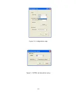
Страница 97: ...Figure 5 1 Configuration setup Figure 5 2 GPIB communications setup 85...
Страница 99: ...Figure 5 4 Virtual Control Panel Figure 5 5 Command Panel 87...
Страница 102: ...Figure 5 7 Calibration Panel Figure 5 8 Firmware Panel 90...
Страница 103: ...Figure 5 9 Modulation Panel 91...
Страница 123: ...Figure B 1 Information Panel Figure B 2 Configure Panel 111...
Страница 124: ...Figure B 3 Reboot in Progress Panel Figure B 4 Web Control Panel 112...


