


MOTOROLA CMOS LOGIC DATA
MC14534B
6–352
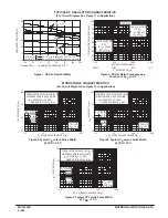
SCANNER TIMING DIAGRAM
NOTE: If Mode B = 1, the first decade is inhibited and S1 will not go high, and the cycle will be
shortened to four stages.
DS5 is selected automatically when Scanner Reset goes high.
TEN
THOUSANDS
THOUSANDS
HUNDREDS
TENS
UNITS
SCANNER
CLOCK
SCANNER
RESET
DS1
DS2
DS3
DS4
DS5
ERROR DETECTION TIMING DIAGRAM
NOTE: Error detector looks for inverted pulse on Clock B. Whenever a positive edge at
Clock A is not accompanied by a negative pulse at Clock B (or vice–versa) within
a time period of the one–shots an error is counted. Three errors result in Error Out
to go to a “1”. If error detection is not needed, tie Clock B high or low and leave
Pins 1 and 22 unconnected.
CLOCK A
CLOCK B
RESET
ERROR
OUT
GOOD PULSE
ERROR
1
ERROR
2
ERROR
3
ERROR
4
GOOD PULSE
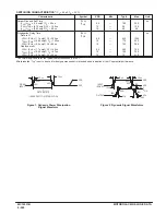
CLOCK SKEW RANGE
NOTES:
1. The skew is the time difference between the
low–to–high transition of CA to the high–to–
low transition of CB or vice–versa. Capacitors
C1 = C22 tied from pins 1 and 22 to VSS.
2. This graph is accurate for C1 = C22
≥
100 pF.
3. When the error detection circuitry in not used,
pins 1 and 22 are left open.
1000
500
300
100
50
30
10
5.0
3.0
1.0
3.0
5.0
7.0
9.0
11
13
15
17
VDD (Vdc)
SKEW IN THIS RANGE
RESULTS IN COUNTED
ERROR.
MAX
SKEW IN THIS RANGE
RESULTS IN NO ERROR
COUNTED.
TYP
MIN
SKEW IN THIS RANGE
MAY OR MAY NOT
RESULT IN COUNTED
ERROR.
ALLOW
ABLE CLOCK SKEW (ns/pF)
Содержание CMOS Logic
Страница 1: ......
Страница 5: ...iv MOTOROLA CMOS LOGIC DATA ...
Страница 6: ...Master Index 1 ...
Страница 12: ...Product Selection Guide 2 ...
Страница 17: ...The Better Program 3 ...
Страница 20: ...B and UB Series Family Data 4 ...
Страница 25: ...CMOS Handling and Design Guidelines 5 ...
Страница 32: ...CMOS Handling and Design Guidelines 5 ...
Страница 39: ...Data Sheets 6 ...
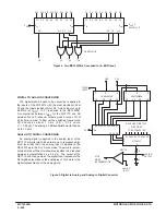
Страница 69: ...MOTOROLA CMOS LOGIC DATA 6 31 MC14008B Figure 5 Logic Diagram Cin A1 B1 A2 B2 A3 B3 A4 B4 S1 S2 S3 S4 Cout ...
Страница 234: ...MOTOROLA CMOS LOGIC DATA MC14174B 6 196 FUNCTIONAL BLOCK DIAGRAM TIMING DIAGRAM ...
Страница 238: ...MOTOROLA CMOS LOGIC DATA MC14175B 6 200 FUNCTIONAL BLOCK DIAGRAM TIMING DIAGRAM ...
Страница 555: ...CMOS Reliability 7 ...
Страница 561: ...Equivalent Gate Count 8 ...
Страница 563: ...Packaging Information Including Surface Mounts 9 ...
Страница 571: ......