


MOTOROLA CMOS LOGIC DATA
6–265
MC14512B
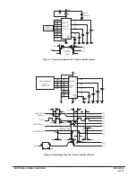
Figure 3. 3–State AC Test Circuit and Waveform
Test
S1
S2
S3
S4
tPHZ
Open
Closed
Closed
Open
tPLZ
Closed
Open
Open
Closed
tPZL
Closed
Open
Open
Closed
tPZH
Open
Closed
Closed
Open
Switch Positions for 3–State Test
Z
DISABLE
INHIBIT
A
B
C
X0
X1
X2
X3
X4
X5
X6
X7
VSS
PULSE
GENERATOR
VDD
VDD
CL
1 k
S1
S2
VSS
VDD
S3
S4
VSS
VDD
VOH
VOL
20 ns
90%
50%
10%
tPLZ
tPZL
20 ns
DISABLE
INPUT
OUTPUT
OUTPUT
VSS
VOH
VOL
10%
90%
90%
10%
tPHZ
tPZH
≈
2.5 V @ VDD = 5 V,
10 V, AND 15 V
≈
2 V @ VDD = 5 V
≈
6 V @ VDD = 10 V
≈
10 V @ VDD = 15 V
LOGIC DIAGRAM
13
12
11
1
2
3
4
5
6
7
9
X7
X6
X5
X4
X3
X2
X1
X0
B
C
A
15
10
14
DISABLE
INHIBIT
VDD
Z
VSS
1
1
IN
OUT
IN
2
OUT
2
TRANSMISSION
GATE
SELECTED
DEVICE
MC14512B
MC14512B
MC14512B
IOD
ITL
ITL
IL
LOAD
DATA
BUS
3–STATE MODE OF OPERATION
Output terminals of several MC14512B 8–Bit Data Selec-
tors can be connected to a single date bus as shown. One
MC14512B is selected by the 3–state control, and the re-
maining devices are disabled into a high–impedance “off”
state. The number of 8–bit data selectors, N, that may be
connected to a bus line is determined from the output drive
current, IOD, 3–state or disable output leakage current, ITL,
and the load current, IL, required to drive the bus line (includ-
ing fanout to other device inputs), and can be calculated by:
ITL
N =
+ 1
IOD – IL
N must be calculated for both high and low logic state of the
bus line.
Содержание CMOS Logic
Страница 1: ......
Страница 5: ...iv MOTOROLA CMOS LOGIC DATA ...
Страница 6: ...Master Index 1 ...
Страница 12: ...Product Selection Guide 2 ...
Страница 17: ...The Better Program 3 ...
Страница 20: ...B and UB Series Family Data 4 ...
Страница 25: ...CMOS Handling and Design Guidelines 5 ...
Страница 32: ...CMOS Handling and Design Guidelines 5 ...
Страница 39: ...Data Sheets 6 ...
Страница 69: ...MOTOROLA CMOS LOGIC DATA 6 31 MC14008B Figure 5 Logic Diagram Cin A1 B1 A2 B2 A3 B3 A4 B4 S1 S2 S3 S4 Cout ...
Страница 234: ...MOTOROLA CMOS LOGIC DATA MC14174B 6 196 FUNCTIONAL BLOCK DIAGRAM TIMING DIAGRAM ...
Страница 238: ...MOTOROLA CMOS LOGIC DATA MC14175B 6 200 FUNCTIONAL BLOCK DIAGRAM TIMING DIAGRAM ...
Страница 555: ...CMOS Reliability 7 ...
Страница 561: ...Equivalent Gate Count 8 ...
Страница 563: ...Packaging Information Including Surface Mounts 9 ...
Страница 571: ......