


MOTOROLA CMOS LOGIC DATA
6–255
MC14510B
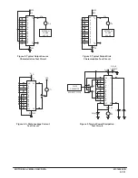
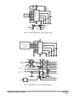
Figure 4. Programmable Cascaded Frequency Divider
Note: The programmable frequency divider can be set by applying the desired divide ratio, in BCD, to the preset inputs. For
example, the maximum divide ratio of 99 may be obtained by applying a 10011001 to the preset inputs P0 to P7. For this divide
operation, both counters should be configured in the count down mode. The divide ratio of zero is an undefined state and
should be avoided.
Q0
Q1
Q2
Q3
Q4
Q5
Q6
Q7
PE
Cin
CLOCK
U/D
P1
P2
P3
Cout
L.S.D.
MC14510B
P1
P2
P3
P4
P5
P6
P7
THUMBWHEEL SWITCHES
(OPEN FOR “0”)
RESISTORS = 10 k
Ω
CLOCK (fin)
+ VDD
RESET
OPEN = COUNT
Q1
Q2
Q3
Q4
Q1
Q2
Q3
Q4
M.S.D.
MC14510B
PE
Cin
CLOCK
U/D
R
R
BUFFER
fout
P0
+ VDD
+ VDD
fout =
fin
n
Cout
P4
P1
P2
P3
P4
Содержание CMOS Logic
Страница 1: ......
Страница 5: ...iv MOTOROLA CMOS LOGIC DATA ...
Страница 6: ...Master Index 1 ...
Страница 12: ...Product Selection Guide 2 ...
Страница 17: ...The Better Program 3 ...
Страница 20: ...B and UB Series Family Data 4 ...
Страница 25: ...CMOS Handling and Design Guidelines 5 ...
Страница 32: ...CMOS Handling and Design Guidelines 5 ...
Страница 39: ...Data Sheets 6 ...
Страница 69: ...MOTOROLA CMOS LOGIC DATA 6 31 MC14008B Figure 5 Logic Diagram Cin A1 B1 A2 B2 A3 B3 A4 B4 S1 S2 S3 S4 Cout ...
Страница 234: ...MOTOROLA CMOS LOGIC DATA MC14174B 6 196 FUNCTIONAL BLOCK DIAGRAM TIMING DIAGRAM ...
Страница 238: ...MOTOROLA CMOS LOGIC DATA MC14175B 6 200 FUNCTIONAL BLOCK DIAGRAM TIMING DIAGRAM ...
Страница 555: ...CMOS Reliability 7 ...
Страница 561: ...Equivalent Gate Count 8 ...
Страница 563: ...Packaging Information Including Surface Mounts 9 ...
Страница 571: ......