3 SIGNALS AND WIRING
3.4 Connectors and pin assignments
67
3
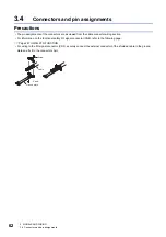
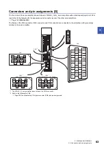
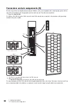
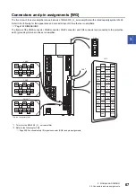
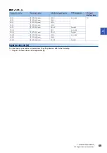
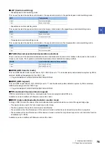
Connectors and pin assignments [WG]
The front view of the servo amplifier shown below is of MR-J5W3-_G_ servo amplifiers with a rated capacity symbol of 222.
Refer to the following for the appearance and connector layout of the other servo amplifiers.
The frames of the CN2A connector, CN2B connector, CN2C connector, and CN3 connector are connected to the protective
earth (grounding) terminal in the servo amplifier.
*1 This is for the MR-J5W3-_G_ servo amplifier.
*2 Refer to the following for CN8.
Page 290 Functional safety I/O signal connector (CN8) and pin assignments
14
LG
LA-A
1
15
2
16
3
17
4
18
5
19
6
20
7
21
8
22
9
23
10
24
11
25
12
26
13
LBR-A
LAR-A
LB-A
LA-B
LBR-B
LAR-B
LB-B
DI1-A
DI2-B
DI1-B
DI2-A
DI3-A
DICOM
DI3-B
EM2
CALM
MBR-B
CINP
MBR-A
DOCOM
2
LG
4
MRR
3
MR
1
P5
6
THM2
8
MXR
7
MX
5
THM1
THM2
THM1
10
9
BAT
2
LG
4
MRR
3
MR
1
P5
6
8
MXR
7
MX
5
10
9
BAT
THM2
THM1
2
LG
4
MRR
3
MR
1
P5
6
8
MXR
7
MX
5
10
9
BAT
CN2A
CN3
CN2B
CN2C
*1
DI2-C
DI1-C
DI3-C
MBR-C
2
LG
3
MO2
1
MO1
CN6
CN8
*2
This is a connector of 3M.
Содержание Melservo-J5 MR-J5 Series
Страница 1: ...MR J5 User s Manual Hardware MR J5 _G_ MR J5W_ _G_ MR J5 _A_ Mitsubishi Electric AC Servo System ...
Страница 2: ......
Страница 441: ...12 USING A FULLY CLOSED LOOP SYSTEM 12 7 Absolute position detection system 439 12 MEMO ...
Страница 445: ......


