242
6 OPTIONS AND PERIPHERAL EQUIPMENT
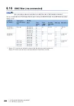
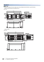
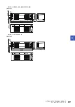
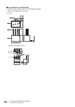
6.17 MR-J3-D05 safety logic unit
■
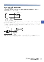
Source I/O interface (CN9, CN10 connectors)
• Digital input interface DI-1
This is an input circuit in which the anode of the photocoupler is the input terminal. Transmit signals from a source (open-
collector) type transistor output, relay switch, etc.
• Digital output interface DO-1
This is a circuit in which the emitter of the output transistor is the output terminal. When the output transistor is turned on, the
current flows from the output terminal to a load.
A maximum of 2.6 V voltage drop occurs in the MR-J3-D05.
*1 If the voltage drop (maximum of 2.6 V) interferes with the relay operation, apply high voltage (maximum of 26.4 V) from external source.
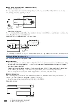
Wiring CN9, CN10 connectors
Be careful when handling tools during wiring work.
■
Stripping wire
• Use wire of applicable wire size from AWG 24 to 20 (0.22 mm
2
to 0.5 mm
2
) (recommended wire: UL 1007 recommended),
and process it so that its stripped length is 7.0 mm ± 0.3 mm. Before using, be sure to check the length of the stripped
section with a gage or other tool.
• If the stripped wire is bent, frayed, or wound too thick, correct it by lightly twisting the wire or manipulating it as necessary,
and check the length of the stripped section before using it. In addition, do not use excessively deformed wire.
• When processing the cut surface of wire and the stripped surface of conductor, make them smooth.
■
Connecting wires
When connecting wires, do so with the receptacle assembly pulled out of the head connector. Wiring while connectors are
inserted in the servo amplifier may damage the connectors or the board.
• Connecting wires with insertion/extraction tool (1891348-1 or 2040798-1)
Dimensions and mass
V
CES
≤
1.0 V
I
CEO
≤
100
μ
A
200 mA
MR-J3-D05
Approximately
5 mA
24 V DC ± 10 %
Switch
SRESA-,
etc.
SRESA+,
etc.
Approx. 5.4 k
Ω
MR-J3-D05
200 mA
If polarity of diode is
reversed, MR-J3-D05
will malfunction.
24 V DC ± 10 %
*1
Load
SDO2B+,
etc.
SDO2B-,
etc.
100
15
7
[Unit: mm]
Mass: Approx. 20 g
Содержание Melservo-J5 MR-J5 Series
Страница 1: ...MR J5 User s Manual Hardware MR J5 _G_ MR J5W_ _G_ MR J5 _A_ Mitsubishi Electric AC Servo System ...
Страница 2: ......
Страница 441: ...12 USING A FULLY CLOSED LOOP SYSTEM 12 7 Absolute position detection system 439 12 MEMO ...
Страница 445: ......

