100
3 SIGNALS AND WIRING
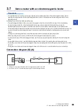
3.7 Servo motor with an electromagnetic brake
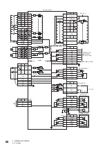
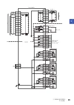
Connection diagram [WG]
*1 Do not use the 24 V DC interface power supply for the electromagnetic brake.
*2 Configure a circuit which interlocks with an emergency stop switch to shut off.
*3 This connection is for the MR-J5W3-_G_ servo amplifier.
*4 Although the diagram shows the input signal and the output signal each using a separate 24 V DC power supply for illustrative purposes,
the system can be configured to use a single 24 V DC power supply.
CALM
DOCOM
MBR-A
EM2
DICOM
RA1
RA2
B
RA5
*2
B2
U
B1
EM2
RA3
RA4
MBR-B
MBR-C
B
B2
U
B1
CALM
RA1
MBR-A
RA2
MBR-B
RA3
B
B2
U
B1
MBR-C
RA4
*3
Servo amplifier
24 V DC
*4
24 V DC for
electromagnetic
brake
*1
24 V DC
*4
A-axis servo motor
B-axis servo motor
C-axis servo motor
Содержание Melservo-J5 MR-J5 Series
Страница 1: ...MR J5 User s Manual Hardware MR J5 _G_ MR J5W_ _G_ MR J5 _A_ Mitsubishi Electric AC Servo System ...
Страница 2: ......
Страница 441: ...12 USING A FULLY CLOSED LOOP SYSTEM 12 7 Absolute position detection system 439 12 MEMO ...
Страница 445: ......


